This thread has been locked.

If you have a related question, please click the "Ask a related question" button in the top right corner. The newly created question will be automatically linked to this question.

INA125: INA125 reference circuit value of LOAD

Part Number: INA125

Hi,

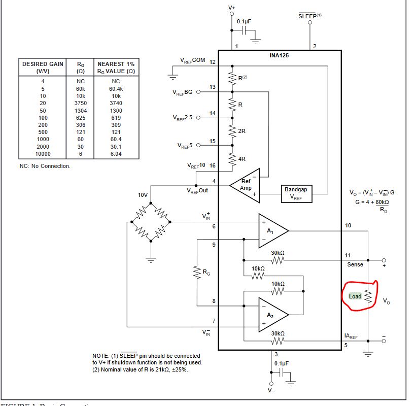
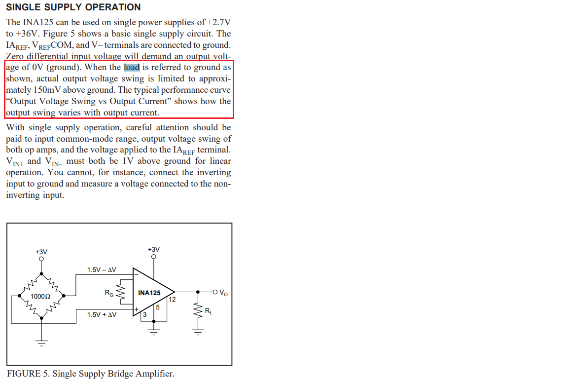
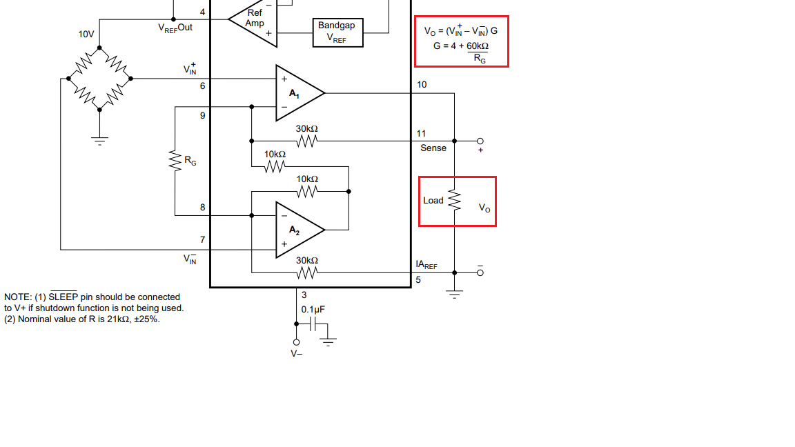
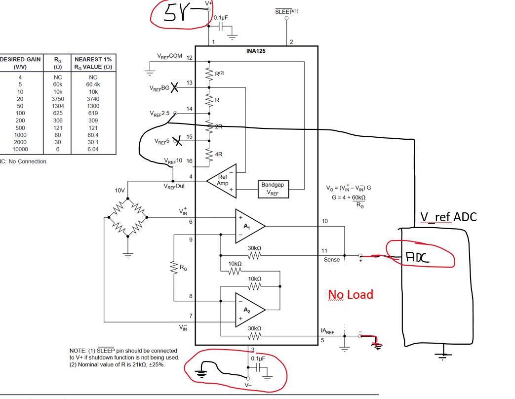
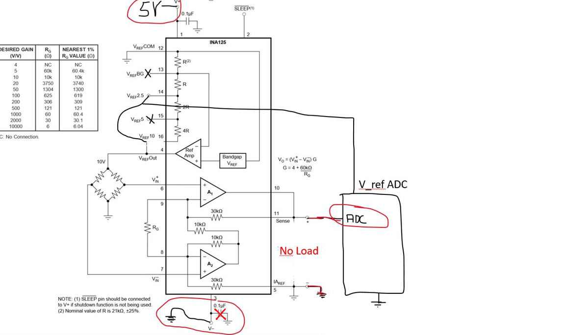
I have a question concerning the reference circuit on page 10 in the datasheet. I use the INA125 Microcontroller

for reading a Wheastonebridge with strain gagues. What is the value of the load I marked red? Furthermore I want to ask

when I have to connect V- ?

Best regards

Fabian

  • Hi Fabian,

    Happy to help! Unfortunately, your image didn't come through, I am unable to click on it. Can you try attaching it again using the "attachment" option in the editor?

    -Tamara

  • Hi Fabian,

    Can you reload your image? I am unable to view  the image. 


    Question: Furthermore I want to ask when I have to connect V- ? 


    I am not sure that I understand your question. You have to connect V-, the input is differential measurement.  Wheatston Bridge input circuit in Figure 10 is a balanced input circuit.  When the circuit is perfect balanced, the output is 0 or Vin+ = Vin- = 5V (input reference voltage = 10V) in Figure 10. The Gain of the circuit is shown in Equation 1. 

    Regarding the Load: If the load is reference to ground as shown in Figure 10, the output voltage swing is limited to approx. 150mV. Then you are able to calculate the Gain through the equation below in red, shown in Figure 10. The selection of output current can be calculated in the bottom of p.7 datasheet via Output Voltage (V) vs. Output Current (mA) plot, which depending on your operating temperature. Once you know the output current, you can calculate the load resistance, 150mV/output_current (mA).

    Best,

    Raymond

  • Thanks for the answer.

    Load: In my data sheet wasn't a figure 10, did you refer to  figure 1 ?
    I added a Microcontroller in the picture with ADC on it. This should be correct as
    I showed it, is it? What happens if I don't ad a resistor (Load) in parallel to the ADC input?

    V-:  The question was concerning to pin 3 (V-) . When I understood you the right way
         you talked about V_in-(Pin 7) . Is this possible?

    Output voltage swing: Is this the maximum difference between pin 6 and 7 ?

    Best regards

    Fabian

  • Hi Fabian,

    If you are using MCU to read Vo at pin 11 of INA125, it will be easier to use single supply bridge amplifier, see Figure 5 in the previous reply. Your output voltage swing will be limited to approx. 150mV above ground. V- or pin 3 of INA125 will be connected to Ground as shown in Figure 5. Your will convert Vo+ to ADC of Micro controller, and Vo- connection is not needed, since the the measurement will be respect to GND. 

    If you are using MCU as load,  then you do not need the Load Resistor shown in the drawing. 

    Best,

    Raymond

  • Hi Fabian,

    I forgot to mention that the MCU needs to have the same ground as INA125, If you are using the single power supply operation, what is your voltage rail. I am trying to increase your output voltage swing, so that you will have better ADC resolution during voltage conversion. 

    Best,

    Raymond

  • MCU has same ground as INA125. Voltage rail of ADC Microcontroller is 2.5V . As Powersuply for the bridge I use 2,5 V of INA125 (Pin14).

    I made a new picture of the schematic. Would this work? Do you see any problems? Is voltage swing limited in this schematic?

  • Hi Fabian,

    It looks good, and 0.1uF at pin 3 is not needed. 

     Is voltage swing limited in this schematic?


    Since your ADC's reference is 2.5V, your voltage swing will be limited from 0.3V to 2.5V. Thus you may need to maximize your ADC counts and set your gain accordingly. If it does not work for your application, you may have to go with 5V Vref and/or change the reference voltage of ADC. 

    Best,

    Raymond