This thread has been locked.

If you have a related question, please click the "Ask a related question" button in the top right corner. The newly created question will be automatically linked to this question.

TLC27M2: TINA TI Simulation of AC Current Measurement using TLC27M2

Part Number: TLC27M2

Hello ,

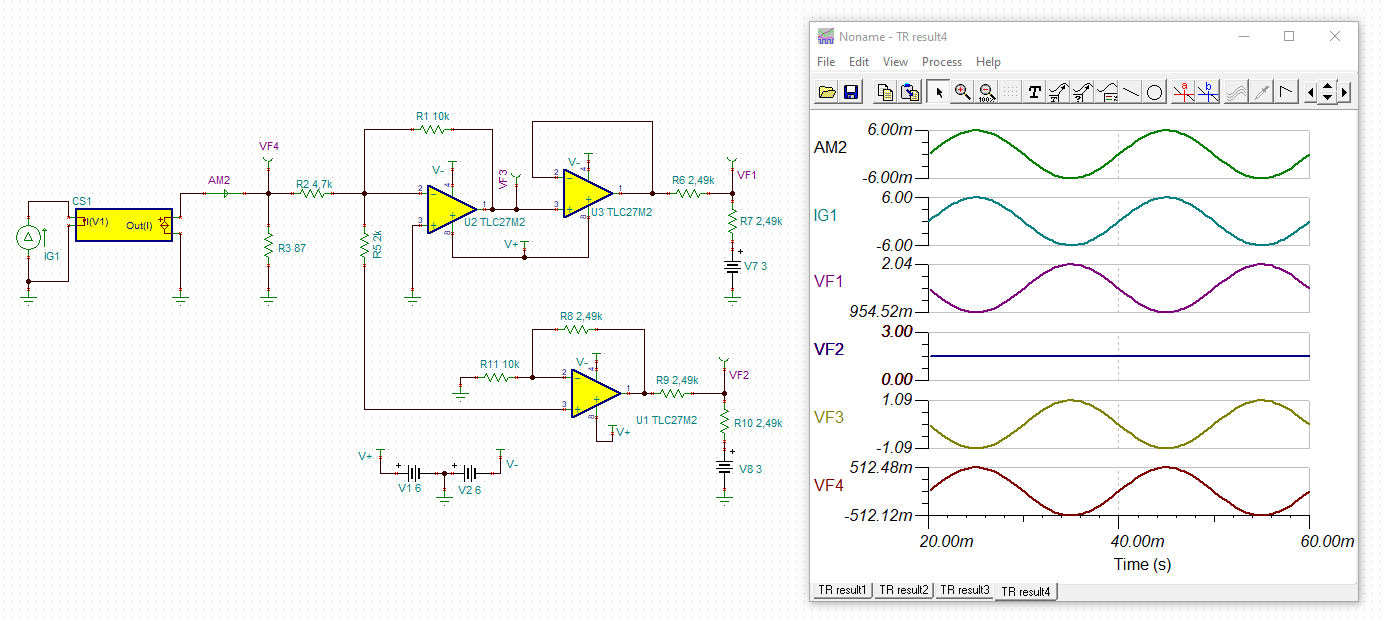
I am simulating AC current measurement circuit designed using TLC27M2. Below are requirements:

1. AC current Range: 0 to 6A , min change of 5mA should be detectable

2. CT:  Class 0.2, Ratio: 1000:1

3. ADC used: 12 Bit SAR ADC, Vref 3.3V

I am attaching Simulation file as well. Somehow I am not getting expected result. Let me know if anything is missing in it.Opamp.TSC

  • Hi Praful, 

    I'm trying to understand your application here. For starters, what is the purpose of "CS1"? Looks like it is just dividing the input current by 1000. The output of U2 will always be negative (inverting amplifier configuration). I don't see the point in using U3 since it is just buffering signal from U2. Also what is is the purpose of U1, because the input is close to 0V. 

    The way your circuit is currently setup, no matter what your input current is, the output is always 3V. Are you looking to build a current sensing circuit? If so, please refer to our "Analog Cookbook Circuit": https://www.ti.com/seclit/sl/slyy137a/slyy137a.pdf. We've multiple circuit examples for current sensing. 

    Please let us know if you need any further assistance. 

    Regards,

    Bala Ravi

  • Hi Ravi,

    Thanks for your reply.  'CS1' is just replica of Current Transformer with Ratio 1000:1. Let me know whether it is right or not.I will go though Cookbook for more ideas on current sensing.

    Regards,

    Prafulla S.

  • Hi Praful,

    As I mentioned before, your schematic as is doesn't have a use case because no matter what your input current is, your output will always be 3V at nodes VF1 and VF2. Are you trying to build a current sensing circuit? 

    Please go over the cookbook circuit, you will most likely find the circuit you want to use along with a working example that you can tweak to fit your application. 

    Regards,

    Bala Ravi

  • Hi Ravi,

    I got you point. I am referring cookbook to build the circuit. I will surely get back to you for queries if any.

    Regards,

    Prafulla S.

  • Hi Praful,

    I think there are two mistakes in your circuit. R7 and R10 shall be 2k49 and not 2R49?

    Also, VF2 isn't showing any AC signal because the +input of U1 is connected to the -input of U2 which sits at "virtual ground".

    praful_tlc27m2.TSC

    Kai

  • Hi Praful, 

    I will go ahead and close this thread for now. Please let us know if you've any further questions. 

    Regards,

    Bala Ravi