This thread has been locked.

If you have a related question, please click the "Ask a related question" button in the top right corner. The newly created question will be automatically linked to this question.

OPA376: OPA376 circuit review

Part Number: OPA376

Hi 

We are using OPA376 to do low side current sensing for battery pack. We build 1000 set using below circuit and see 50 pcs does not work correctly. With replace new device on OPA376 the bad unit work correctly. We are wondering if there is something wrong with our circuit attached below. Can you help review, if any idea what may happen? 

Below is our test result: 

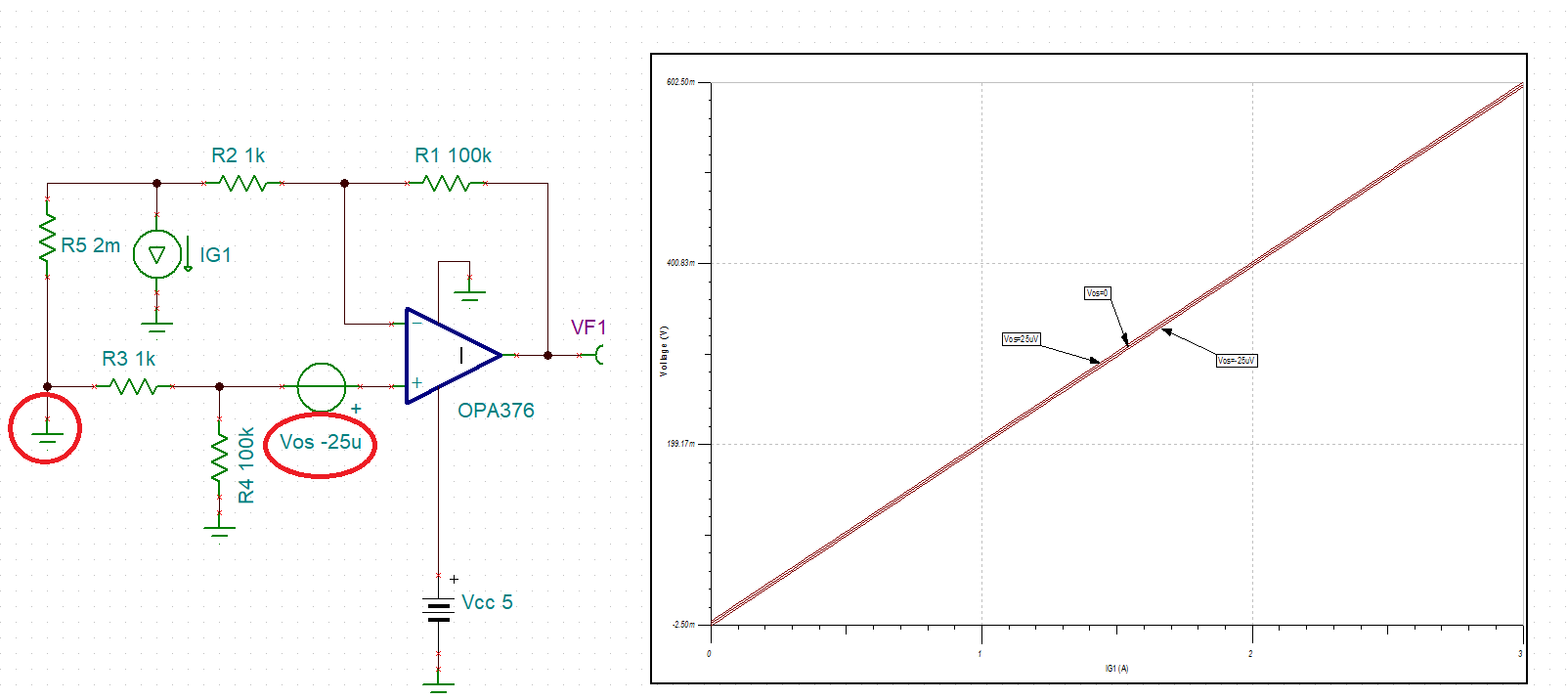
1. Current flow in charge current direction (see the circuit below) . We get the below test result at U6 output, the Red line is what we expected and blue line is the result we get.


1. Current flow in diss-charge current direction (see the circuit below) . We get the below test result at U5 output, the Red line is what we expected and blue line is the result we get.


  • Hi PYTsai,

    just to confirm that no one else is the wrongdoer: Is R135 = R136 = 0 actually? What happens, if you disconnect U5 when charging? Is U6 working properly then?

    Well, I think it has to do with the input offset voltage of OPA376. Take care, the ultra low input offset voltage of 25µV max is only specified for a common mode voltage of mid-supply. At a very low input voltage the input offset voltage can be somewhat higher, as figure 23 of datasheet shows. (Keep in mind that figure 23 is only showing the typical performance):

    So, your input signal of 0...6mV might just be too small compared to the input offset voltage of OPA376 at ~0V input voltage.

    Kai

  • The input voltage offset, Vos, of OPA376 effects the output voltage range of your application.

    For the low-side measurement, the error is small because is limited by the maximum Vos of +/-25uV, which in the gain of 100 means +/-2.5mV error at the output - see below.

    However, for the high-side measurement the input offset voltage is much higher.  To replicate your measurement it would take Vos of -2.25mV - see below - which in the gain of 100 translates into 225mV error at the output matching your measurement. That's why I believe that your actual circuit is a high-side measurement where offset may be in the range of several mV - please double check the connection shown in red.