This thread has been locked.

If you have a related question, please click the "Ask a related question" button in the top right corner. The newly created question will be automatically linked to this question.

PGA281: Why the signal frequency is varied when through PGA281

Part Number: PGA281

Giving PGA281 an 10mVpp 400khz input sinwave signal, it output a 19khz sinwave signal with  12dB attenuation,Why the signal frequency is changed?

  • Hello,

    The PGA281 is a high precision instrumentation amplifier, with very low offset, low drift and small gain error.  These type of devices are typically used to measure relatively low frequency signals and its optimized for DC performance.  Applications include strain gauge, process control, 4-20mA PLC inputs, where relatively low frequency signals are measured that require a high level of DC precision.

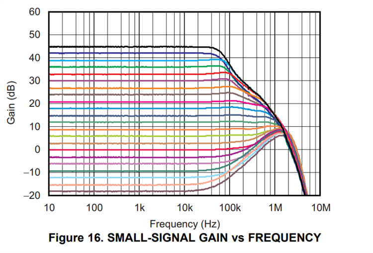
    The small-signal gain vs frequency response is shown on Figure 16.  At the higher gains or attenuation, the frequency response remains flat to somewhere around 20-kHz, and the gain/attenuation will start to decrease as a function of frequency; as shown below, therefore is not intended for high frequency signals. 

    It also uses a chopper stabilized input amplifier (auto-zeroing technique) for excellent DC stability (low offset), over temperature, removing flicker noise, where the chopping amplifier frequency is approximately 250-kHz (based on the 1-MHz clock, discussed on page 14 of the datasheet). Therefore due to both the small-signal frequency response (limited to ~20-kHz depending on gain/attenuation), and due to the chopper amplifier operating at 250-kHz, the device will not be able to work with a 400-kHz input signal. 

    Thank you and Regards,

    Luis