This thread has been locked.

If you have a related question, please click the "Ask a related question" button in the top right corner. The newly created question will be automatically linked to this question.

200us pulsating square wave genetared from MSP430 output port is to be amplify to 80Volts and 60 Amp to drive 1K load using 9V external Battery, Want circuit diagram


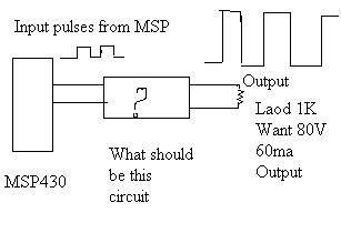
my input : square wave of pulse width 200micro second from MSP430 port.

Battery of 9V.

My output should be : Square wave of 80V  amplitude and 60mA current.


  • Chandrashekhar,

    Are you planning to use a standard "PP3" type 9V battery? This is a huge amount of power to expect from this type of battery and very unlikely to be practical.

    I'll assume for now that you have a 9V power source with plenty of power available (not a PP3 battery). I think the best way to create this output would be with a boost-type switching regulator. The 80V DC output voltage of the boost regulator could then be switched to the load with a power MOSFET switch.

    I believe you should carefully evaluate the power requirements from your battery, first. Then submit a question to our power management forum to get their recommendations on a 9V to 80V boost converter.

    Regards, Bruce.

  • Q1) Is this circuit fine for boosting voltage problem?

                            This is 3v to 80V DC-DC boost converter (Ref: focus.ti.com)

    Q2) How i should convert output from above circuit (80V,5mA DC output)  to suare Pulses of 200us(80V, 60mA) which arrive after everty 20ms {. i.e. frequency of pulse waveform is  is 20HZ and width of each pulse is 200us}