


Other Parts Discussed in Thread: TLV3501, TRF37D73, OPA656
Hey everyone,
my last great experiences in this forum encouraged me to ask for help again. This time I am looking for a solution concerning Silicon Photomultipliers (SiPM) from On Semiconductor. A general scheme of the device is shown here, all other information can be found in the datasheed and the application note from ON which are sofar my only reference...

Application Note Biasing and Readout
Now, we want to use such a sensor for fluorescence detection, ideally for ultra-low light applications. These SiPMs from ON Sem have two possible outputs, called Fout and Sout in the image above which stands for fast and standard output, respectively. The Fout pin allows access to ultra short pulses with FWHM values of about 1-2 ns (as seen next to the schematic above, as we plan to use a bigger SiPM the pulse width will be more in the range of 1-2 ns). We have two ideas in mind to access both outputs - the Fout for singe pulse counting and the Sout for trans-impedance current monitoring. I have drawn a little scheme:

The whole thing is divided into two sub-circuits, CIRCUIT A for the Fout readout and CIRCUIT B for the Sout readout. I want to stress that we are not planing to use both readout circuits simultaneously! When reading the Fout path, the otherwise to the TIA connected Anode will just be shorted to ground as recommended in the application note linked above. If CIRCUIT B is used, the Fout port will be left floating.
CIRCUIT A:
I already designed a circuit build around the OPA858 amplifier with a gain of 100 followed by an ultra-fast comparator TLV3501. The TINA-SPICE results are shown here:
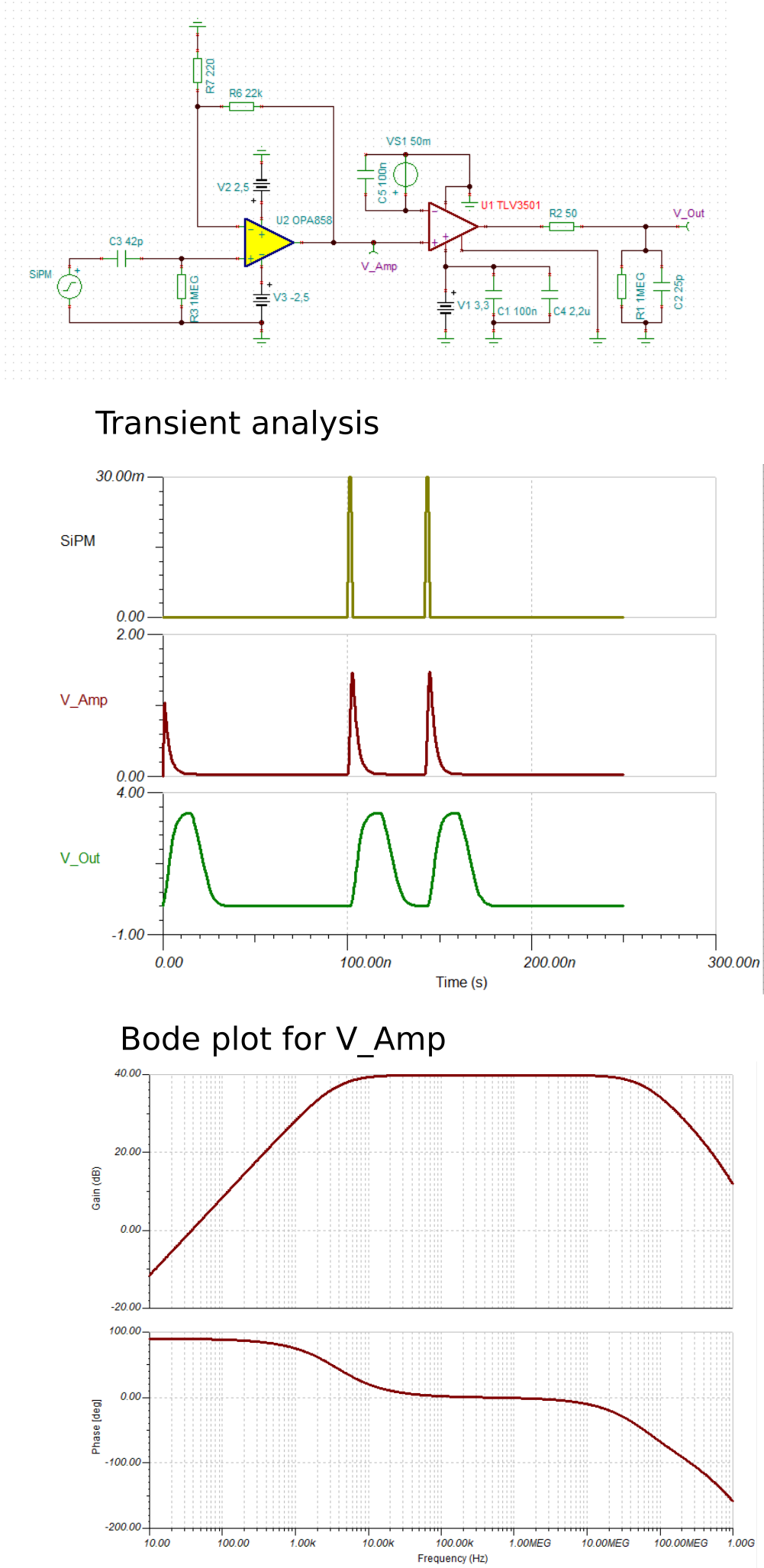
The simulation runs well, however, the whole thing does not work. I tested the amplifier itself, which seems to work the way it should, only with quite some noise which I do mostly blame on my poor equipment (only Digilent AnalogDiscovery 2 for all testing at home). Now the TLV3501 does really weird stuff, but I suppose I messed up something along the way. At this point I am about to belive that I somehow damaged the SiPM and/or other ICs during soldering - I jused the J-Series SiPM here which is BallPad and not very easy to handsolder. However, I thought before going into re-design I ask here if this circuitry is at least plausible.
Is the OPA858 a good choice? In the internet there is literally no description of the use of this Fout port whatsoever. ON Semiconductors describes the use of two Mini Circuit ZX60−43S+ 20dB RF amplifiers in series as their testequipment. I was thinking about the use of a TI RF amplifier like the TRF37D73. However, for larger than 1x1mm SiPMs the Fout is NOT able of driving a 50Ohm impedance. But this circuit is matched internally for 50Ohm and I have no idea other than using an OpAmp for impedance matching. The coil used for the evaluation boards is, unfortunately, not available to buy. Would anybody suggest a different OpAmp or approach? Or should I ask this specific part of the question in the RF forum again?
CIRCUIT B:
For the TIA part, the Application Note gives an example using an OPA656 as amplifier.

Would the OPA858 be better suited to do the job? Just pretty much like in the example circuit from the datasheet below. The OPA858 has a higher GBWP, lower Input Bias Current and Input Voltage noise and comparable max output driving current.

It would be great if you can help me on these questions - I am thankfull for any suggestions!
Regards,
Ben
EDIT: missing images inserted
