This thread has been locked.

If you have a related question, please click the "Ask a related question" button in the top right corner. The newly created question will be automatically linked to this question.

LM1875 As an Op Amp, Noisy Output

Other Parts Discussed in Thread: LM1875, LM675, OPA544, LM3886

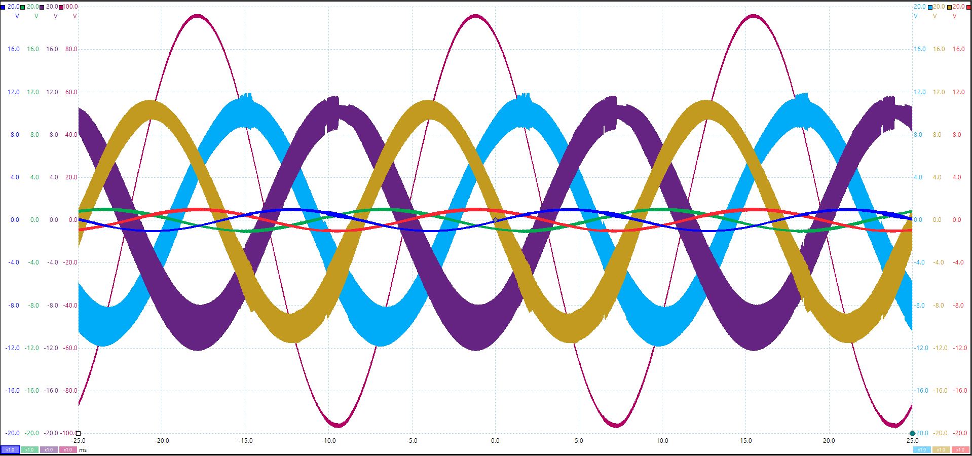
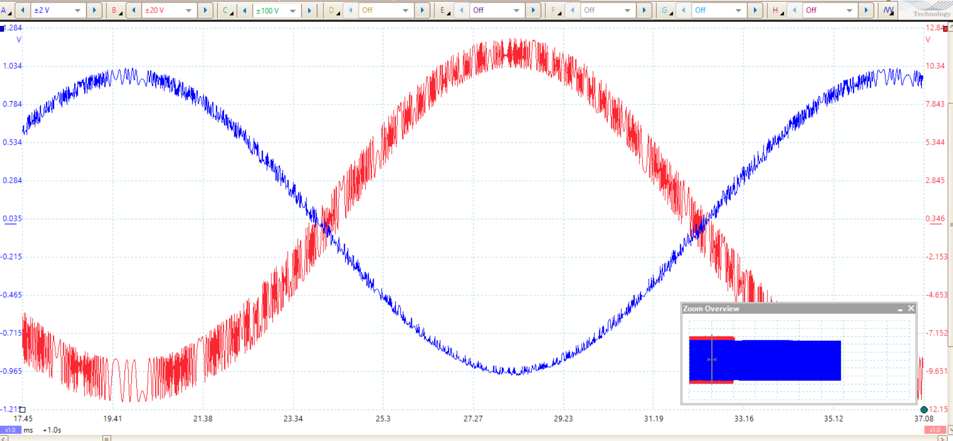
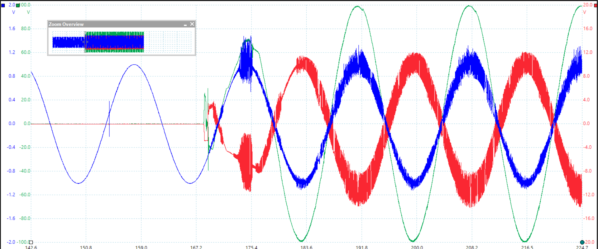
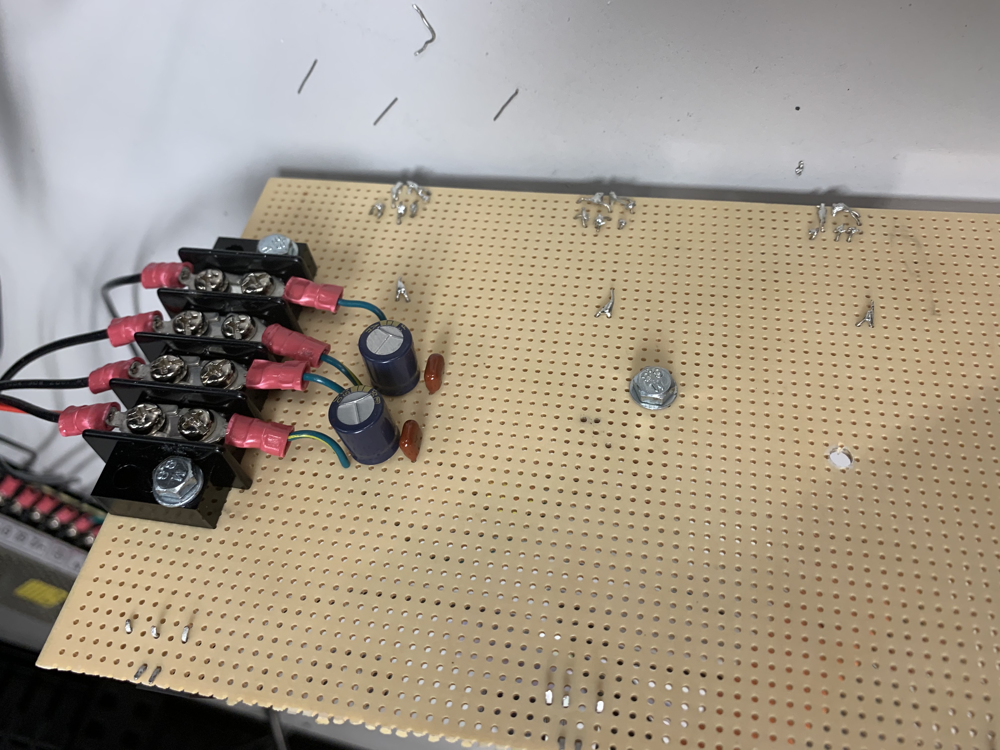
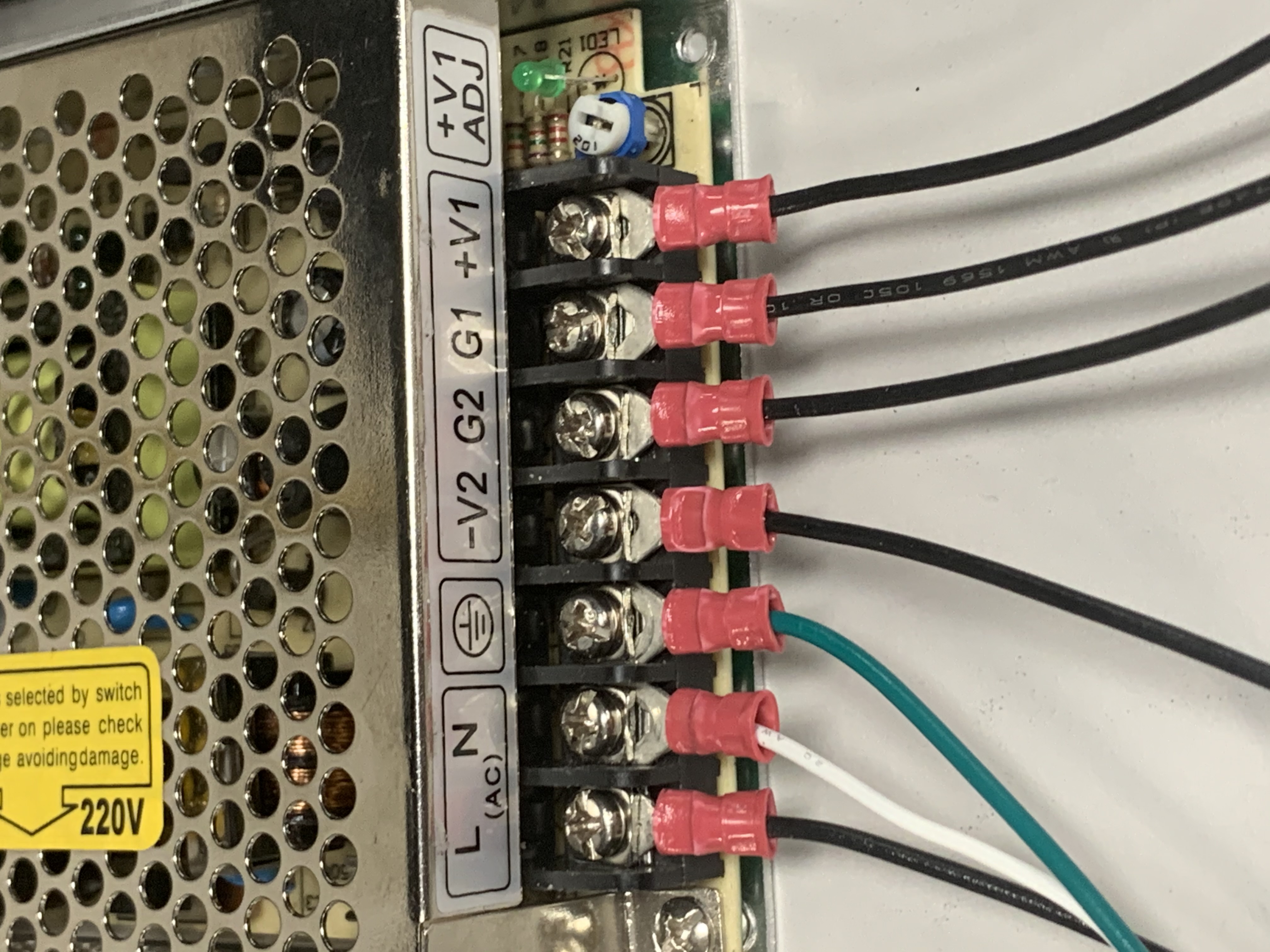
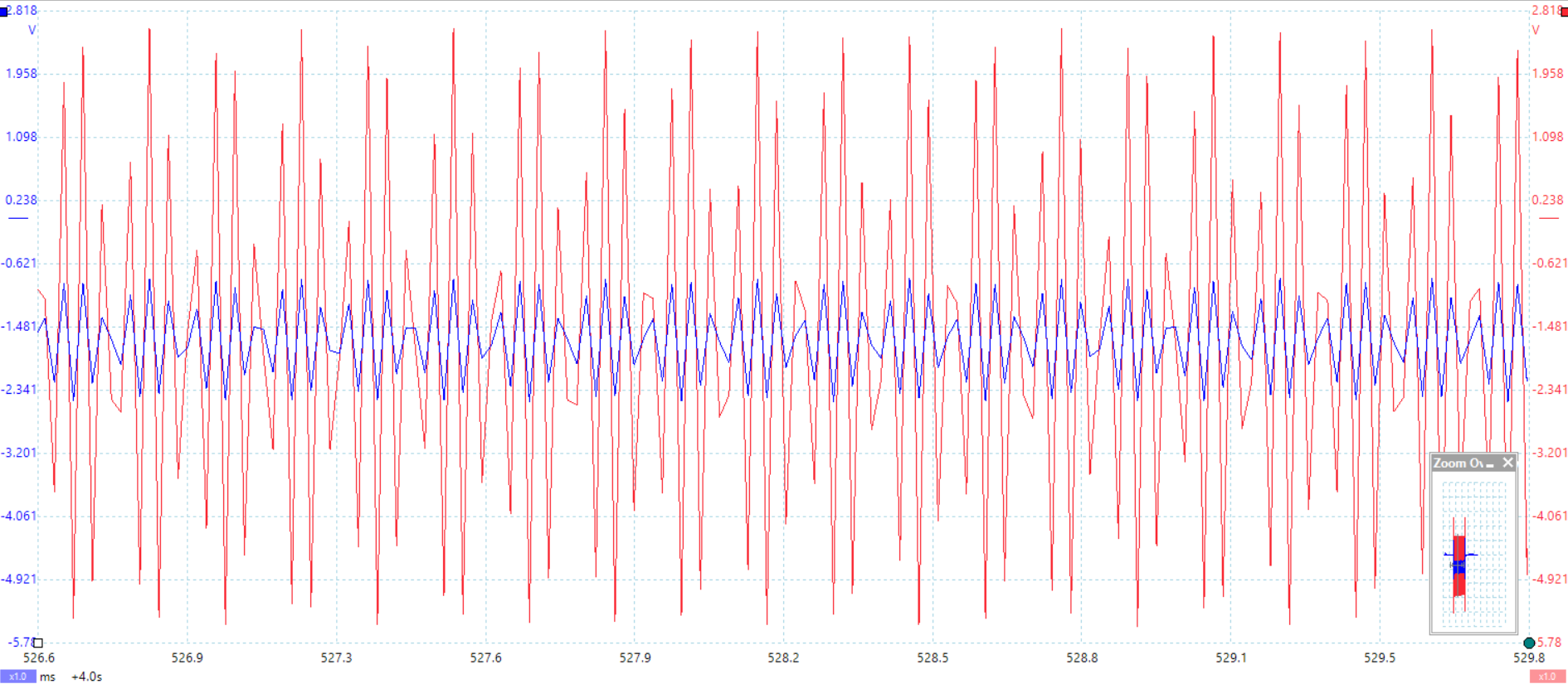
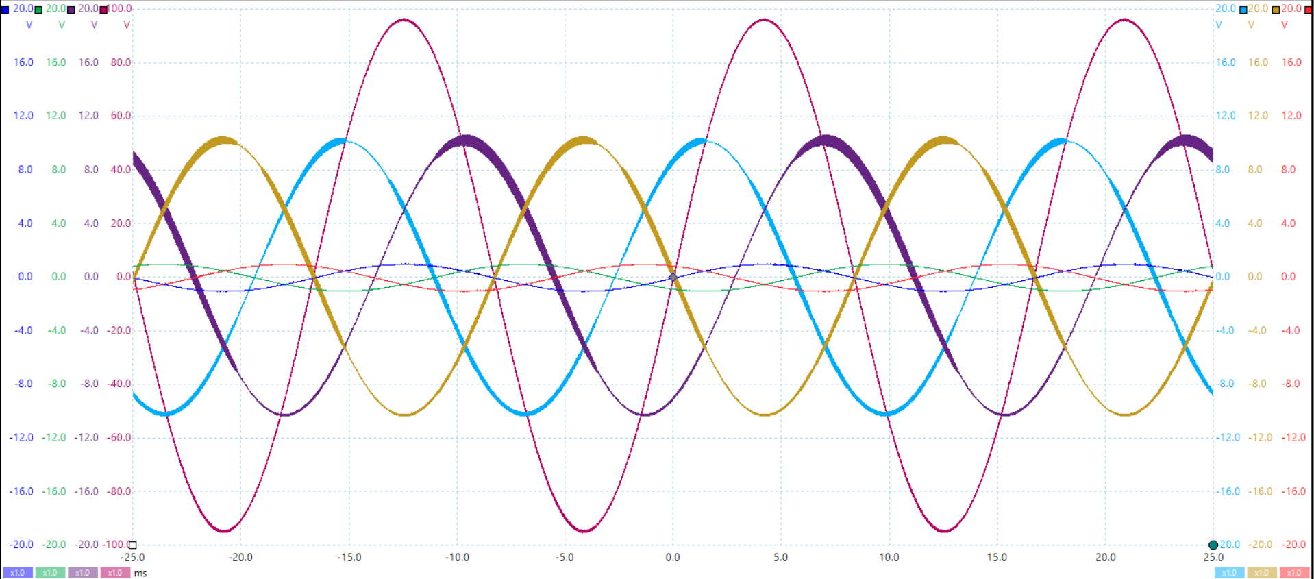
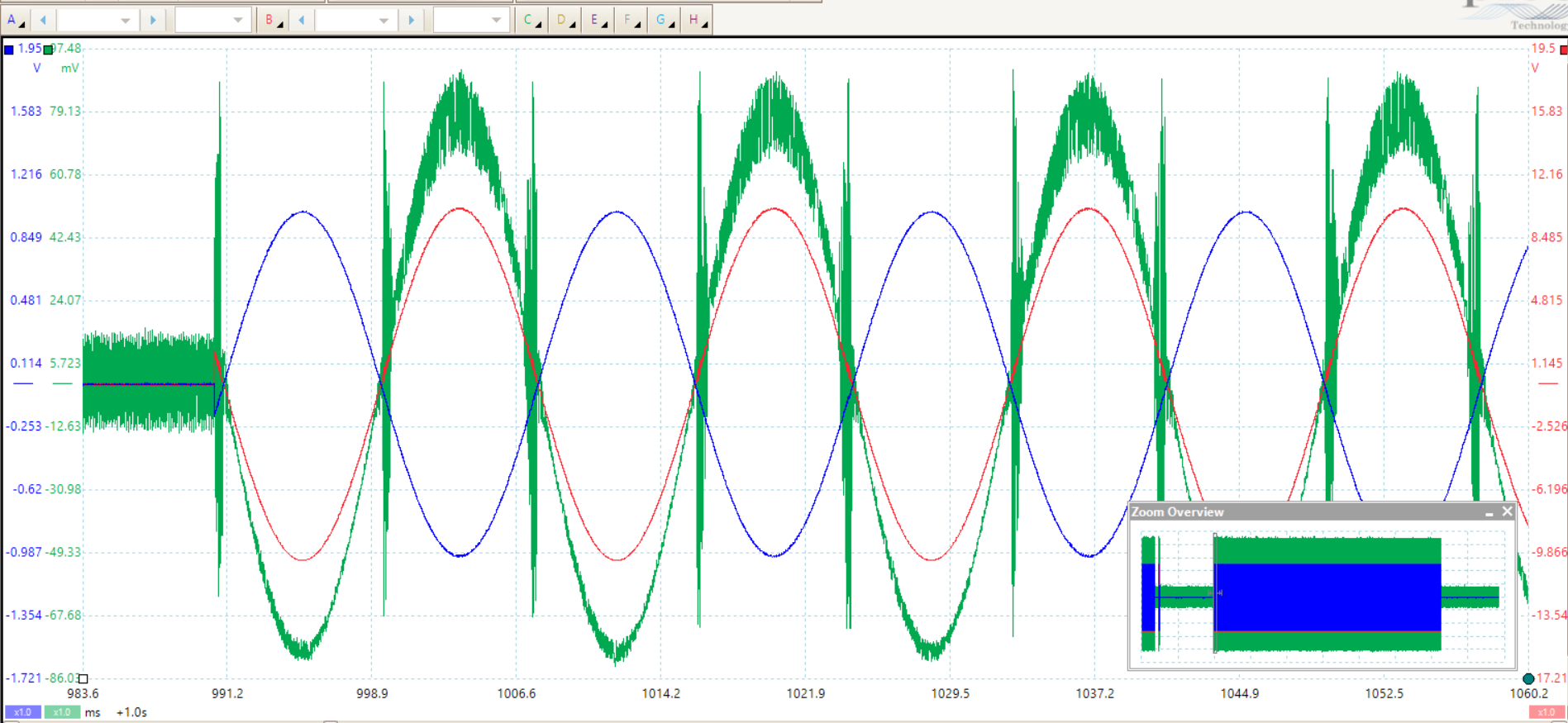
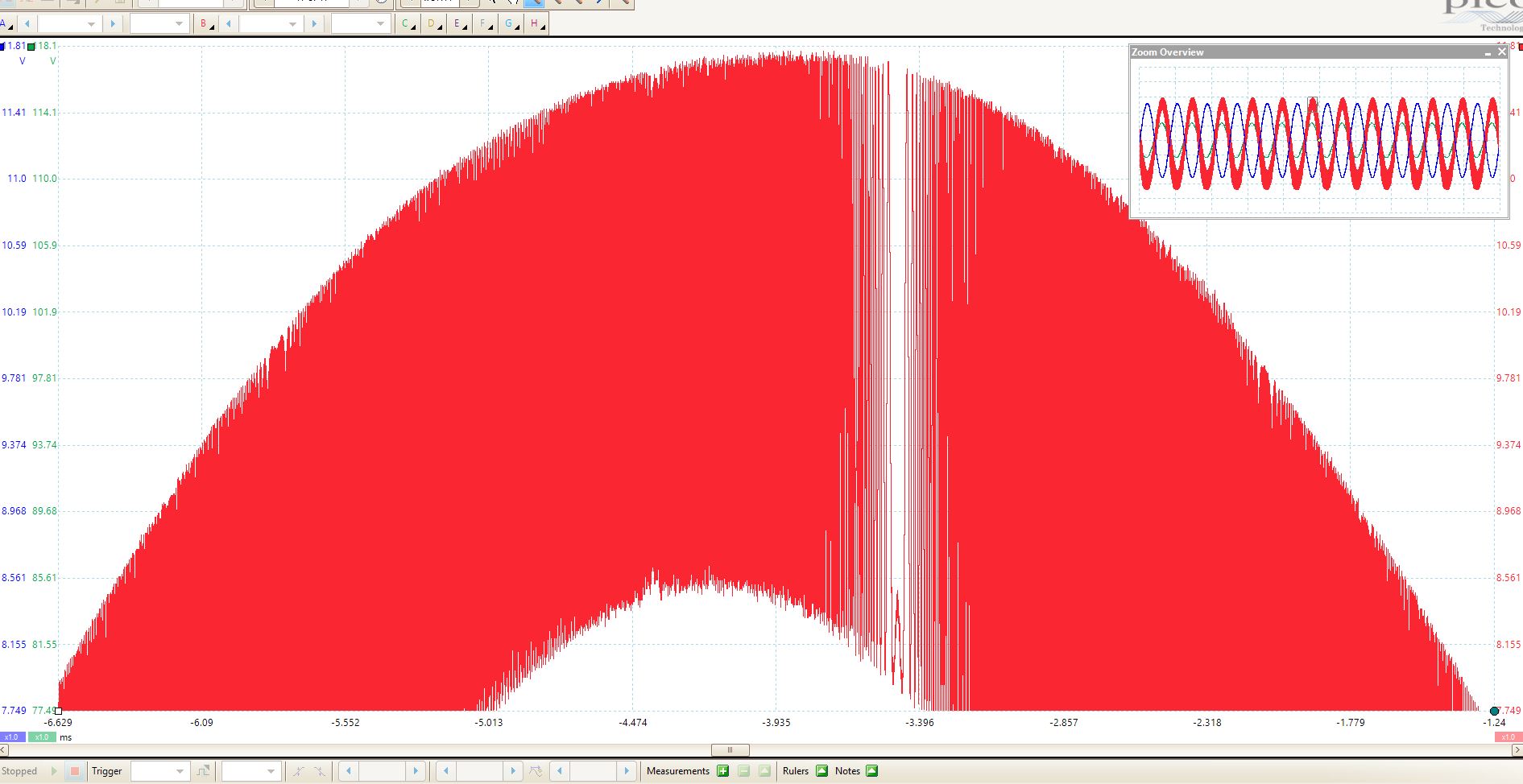
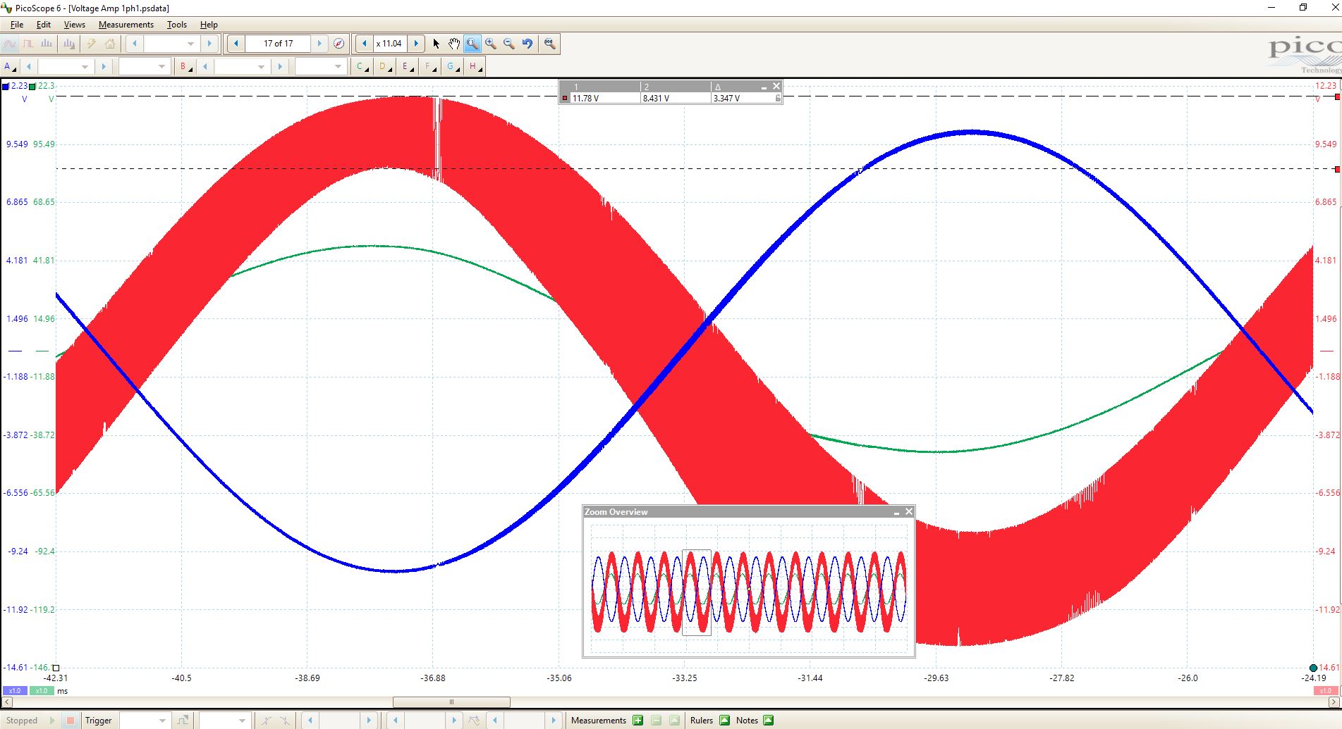
I am using this as a high power, unity gain inverting op amp but my output is very noisy causing some worry about my design. My power supply seems okay, little bit of noise but nothing like the full 4 volts of noise coming out of the amplifier. The noise looks almost like radio waves with how the frequency is changing throughout the wave but I have no idea where this would be coming from nor do I know how to deal with it. I've grounded my heat sinks and linked the grounds of the generator and the supply. I am not sure what else to do to deal with this noise.
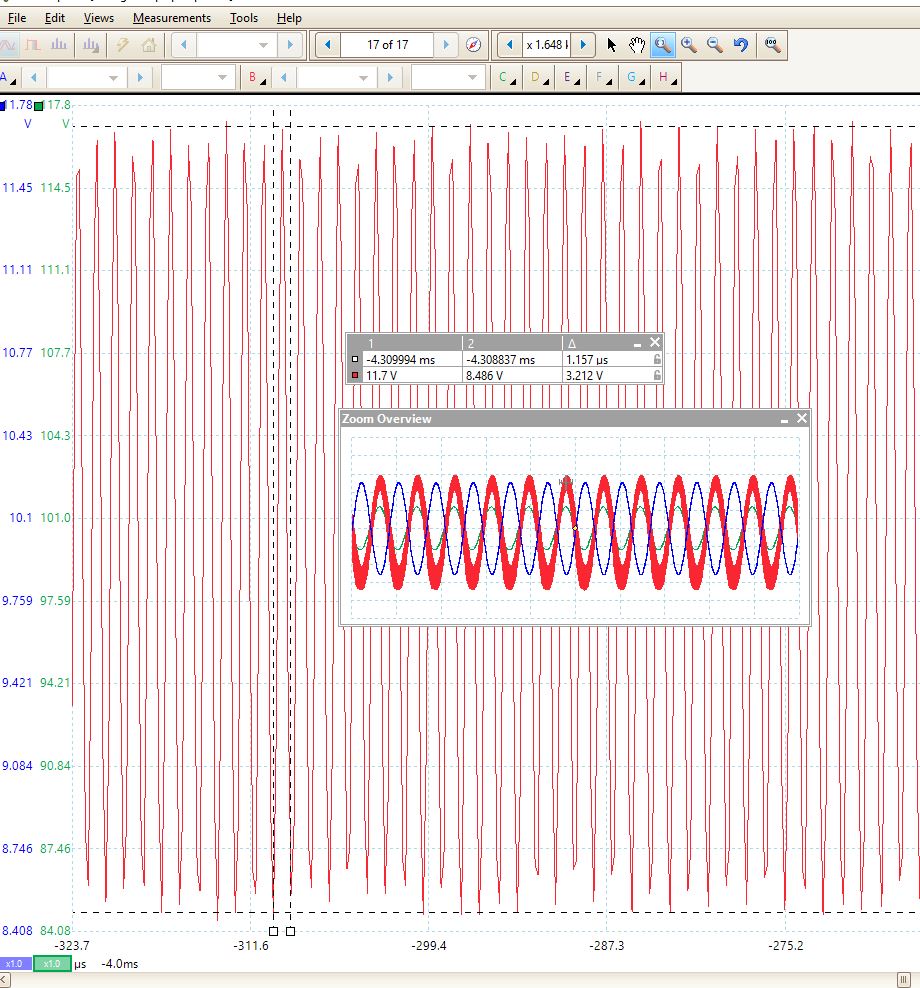
  • Hello Matthew, 

    Can you share you schematic? Additionally what is your load?

    All the best, 

    Carolina

  • This is with an open load. The load I will be using is the low side of a transformer. The signal looks the same with and without a transformer. The schematic is about the most basic unity gain, inverting amplifier you can get. I am using 50k ohm resistors. I noticed the LM1875 is designed for gains more than 10 which could be my issue. I am not sure yet.

  • HI Matthew,

    Yes. The LM1875 is designed for noise gains of 10 or greater. Operating at unity gain will result in exactly what you are seeing...

    The LM675, the LM1875's sister "power op amp", shows an example of how to use it at gains lower than 10 in figure 12 of the LM675 datasheet - essentially adding noise gain and then throwing it away with the added R-C network, so the noise gain is 10, but the signal gain is 1.

    Also do not forget the "snubber" resistor and capacitor on the output - this will keep it from "squeaking" under some conditions - but beware of dissipation in the snubber cap and resistor if you are passing continuous high-frequency, non-audio signals. And ground the output RC network to the POWER ground (where the load would return) and nowhere near the input ground! Star ground is a must with this device...


  • The noise is quite different but still present at a gain of 10. Would I need to add more gain to it even more than this? Red Blue and Green are Vin. Purple Yellow and sky are Vo and Maroon is on the other side of my transformer load. The other load I plan to use is a 40 ohm resistor which at 4 Volts of noise that will make the current quite unstable.

  • Hi Matthew,

    Can you provide a full schematic, and maybe a picture of your layout? Please show your loads, too.

    I hope it is not on a breadboard...This device can be sensitive to layout, ground loops and supply bypassing. You actually do NOT want to ground the supply and the generator together off the board. They must all be grounded at one point on the board ("star ground").

    As an experiment, you can try increasing the gain to say 15 or 20 and see what the oscillations do.

    If you have not done so, read the LM675 datasheet applications section. It has more info than the LM1875 datasheet.


  • Hi Matthew,

    without a schematic we are "blind". So, please post a complete schematic.

    Kai

  • Unfortunately it has to be a breadboard for the time being or at least until I get it working well enough to get a pcb made. This will not be a production board, it is just a tool I was hoping to use on the side. The problem statement was to find a way to generate 3 phase voltage as well as a few other signals that I do not need to amplify. I do not see where I could get any circulating currents on my ground rail because there's no completed circle. I'm not sure how I could rewire the grounds in this setup because there are so many of them. I am only operating at 60Hz so its not like I'm using really high frequencies either. I can make Vin whatever I want from 0-10V but my Vo is limited on my supply.

  • Hello Matthew,

    Yeah...most likely it is layout and supply bypassing related.

    Even though you are "only" running 60Hz, the amplifier GBW is in the MHz, so it is still sensitive to high frequencies from the inputs and suplies. Try putting a 1000pF cap across the feedback resistor to limit the amplifier signal BW.

    The AC "circular path" is from the load through the bypass capacitors to ground. If three amplifiers are sharing the same bypass caps - that will cause major issues.

    Each amplifier should have a 100nF ceramic capacitor DIRECTLY from each supply pin to the power ground.

    I have had bad luck using these amps on a breadboard - especially when starting to source high power. The lossy, and usually poor (or damaged), connections in the sockets create ground loops and poor connections. I build the amps "dead-bug" on a solid copper clad board.

    As an option, there are some premade (and kit-form) LM1875 or TDA2030 amplifier PCBs on eBay and Amazon for a few bucks. Three of these may be a cheaper alternative to making your own board. The tighter layout and already-tested aspect may make the project easier. Just make sure that it is not "bridged" - that would involve modifying the board.

  • Thanks for the tips Paul,

    So just to go over the circulating current point then, would you think using amp female pins to connect the ic pins would add to the noise issue then? The image is what the signal looks if the wires are just sort of hanging there. Its less noise but still something going on, I do not think it has to be perfect. I'm just not sure if I should just stop here or keep trying to make it cleaner.

  • Hi again Paul,

    I'm just a little confused as to why I need bypass caps. I do not want any DC current through my loads, I only want AC. If I use a bypass cap then wouldn't I be shorting my AC signal to ground? After I used the cap across my + and - nodes everything became clipped.

    I am also a little confused as to what negatives I am supposed to tie to the Star ground scheme and what grounds I don't. My whole circuit has been using the virtual ground of my +-15V power supply.

    Either way this noise will only come into play on my 30 ohm load because the current will cause my .1 ohm resistor to swing 26mV to 40mV and I'm not sure how my IC will report that type of voltage.

    Thanks

    Matthew

  • Hello Matthew,

    The bypass caps I am speaking of are on the supplies - not in the audio chain. They provide the "AC" ground for the supplies.

    Think of the amplifier as a motor with a heavy, unbalanced load. If the motor starts quickly, and has weak supports, the motor will "tork" and twist in it's mounts relative to the floor (ground). The faster it goes, the more vibrations.

    The long supply leads are the weak mounts. The bypass capacitors are the "braces" that provide a solid  mount. But all those "braces" do is transfer the vibrations to the floor (ground). If the ground is not secure or flimsy, the vibrations just continue in the floor.

    That is why you want a solid ground  (groundplane & thick traces) and short leads on the caps. You do not want to "feel" anything in the floor. If the positive input "feels" any vibrations in the floor, it will be amplified and go out the load, then back in the floor, then back out the load amplified even more, and that is an oscillation.

    At high frequencies (>1kHz), the currents are passing through the caps, not the supply. Keep in mind  there can be several AMPS of peak current going through the caps depending on the load and frequency.

    So *everything" on that schematic, that has a ground symbol (on the primary side), needs to be connected to the SAME point. The point needs to be a big, thick slab of copper or a thick wire and soldered. You want that point to be a "rock". That means the supply ground, transformer (load) ground, both of the bypass caps, the positive input and the ground from the generator ALL connect to the same physical point. Each of the three amplifers supply ground should tie at the supply ground.

    Grounding multiple power amps is a semester course in frustration. Just ask any theater sound guy...

    Digital scopes "alias" the oscillation, and can make it look better or worse depending on the frequency and time scale.  It is better to look at the oscillation on an analog scope if you have one to see if the "fuzz" you see is noise or a high frequency oscillation.

    With the power off - do you still see the noise?

  • The ground on my breadboard was just the built in bus but what I actually needed was a hunk of metal. Do you think a molex 5 position terminal block with each spot jumped would work? I am trying to work with supplies that we have in house.

    So I did already have one bypass cap I just needed another ceramic one. Got it. My power supply is 2 Amp limited with a 3 amp fuse inside so there shouldn't be much current.

    The noise only appears while the amps get power. Attached is the signal on my previous breadboard setup. I am currently building the circuit on protoboard.

  • I am having a bit of a hard time finding a ground point, and I'm not even sure if I did this correctly but clearly not because now the power on noise is worse now than ever. I ended up just using a bunch of ring terminals and a bolt.

  • HI Daniel,

    Wow! You love crimping!!

    That is not an ideal layout...You are assuming that this is a DC layout. The amplifier is capable of several MHz, so you need to layout the circuit as if it was high frequency AC circuit. This means minimizing lead lengths between components and grounds.

    You cannot dasy-chain the supplies and share a single set of small bypass caps. Each amplifier should be an individual module. The only thing they should share is the central ground point.

    Each amplifier should have it's own pair of ceramic 0.1uF bypass caps to the central ground point.

    The small value bypass capacitors you are using seem to be film capacitors. These are not good for high frequencies. The capacitors MUST be ceramic (and they are MUCH cheaper than the films!).

    You can probably salvage this...You can run a thick bus wire from each amplifier to the central ground post. So run a thick (12-14 ga) bare wire from the central post to each amplifier.

    At each amplifier, connect each of the two ceramic bypass caps to the bus with as short of lead-lengths as possible. You can easily do this from the underside. You can leave the power leads as they are - but each amp needs it's own bypass caps.

    At each amplifier, connect the "+" input and the GND of the generator output to the bus bar.

    In short - to get rid of the oscillations, the grounds need to be solid and short, and each amplifier needs to have a ceramic capacitor from each supply to the GND of that amplifier.

    Dont' worry...Audio amps can one of the most frustrating of circuits to build, with the combination of wide bandwidth, nasty loads and high power. You are not the first to have problems. :^)

  • Hi Matthew,

    I would build up this circuit below thrice:

    Or eventually this improved version with input filtering:

    Use the layout shown in figure 14 of datasheet.

    A very nice layout and a hum loop avoiding circuit can also be seen here:

    Mount these three printed circuit boards upright and next to each other onto a copper-laminated circuit board and use the copper plane of this circuit board as central ground "point".

    Connect the signals to and from the coils as shown below:

    Feed the input signal to the left of layout ("Vin") and also connect the signal ground there ("-"). Avoid the input signals forming any loop areas. Best use screened cables for the input signals.

    I would run input signals of sufficient high amplitudes to the boards and divide them down to the appropriate level by the help of a resistive voltage divider mounted directly at the input of LM1875.

    Kai

  • Hi Paul,

    Through my search of finding thick bus wire I was able to find some bare 12 awg copper wire, its really quite hard to shape it the way I want and getting solder to stick to it, but I also found some thin copper tape. Would that work as a ground plane for this device instead of the thick copper wire?

    And I don't need the 100uF electrolytic cap at all? Is there a reason the applications schematic includes those caps? 

    Also, I cannot seem to find ceramic caps of the correct size, is there a big difference between ceramic and film in this situation? Unfortunately the largest ceramic caps I could find are 5.6nF, would those work instead?

    Thanks,

    Matthew

  • Hi all,

    If I would have to scrap this build and start with a fresh design, is there a different amplifier you would use? The one circuit needs to drive 3 phases of about a half an amp each through a 30 ohm resistor and then this transformer load here. All 60Hz straight AC. I am using a daq system to generate these voltages but the daq doesnt have the capability of that much current.  If the 5.6nF ceramic caps don't work then I'll have to order the 100nF caps anyways. I've done a lot of research on cheap amps and it seems audio amps were the only ones cheap enough and able to drive this much current. The other power op amps were quite a bit more expensive. Maybe a different type of protoboard as well? Paul mentioned a copper clad board, are those just a protoboard with a ground plane on the one side?

    Thanks

    Matthew

  • Hi Matthew,

    Yes. You can also use the copper foil - just be sure it is wide - at least 1cm wide. The idea is to create a low resistance, low inductance path - and that means lots of copper.

    I built my boards on copper clad board - hand wired Jim Williams/Bob Pease style. Copper clad is just a PCB that has not been etched yet - just FR4 with copper on one or both sides. You can buy blank PCB's from most electronics suppliers.

    You need the electrolytic caps for "bulk" (low frequency) bypassing, but it is the 100nF that stops the high-frequency squeaks.

    Once tamed, the LM1875 should work fine.

    I have also used the LM3886 and OPA544 in the past. The OPA544 has the advantage of being unity-gain stable (Av=+1 is okay) and is a little more stable, so you can use it as a buffer, but you have to watch the input and output swing limits. The LM3886 is a monster, and if you are having issues with the LM1875 oscillating, it can be worse with a bad layout. The OPA544 is closer to the LM1875, and you may want to try the OPA544 if you are going to re-do.

  • Thanks for the help Paul,

    My Signals for my transformer load look monumentally better. 

    Unfortunately swapping my load out for the other load, a .2 ohm resistor in series with a 36 ohm resistor, across the .2 ohm resistor I get a blip at the zero cross which may screw up my power factor calculation. Here's what it looks like. I'm not sure if anything can be done about it, if so great, if not I'll manage. I haven't really built the circuit for that setup yet so it would be easy enough to redesign that circuit. 

  • Hi Matthew,

    at least add the obligatory 100µF and 100nF decoupling caps to each LM1875. And don't forget the Zobel network as shown here:

    Kai