This thread has been locked.

If you have a related question, please click the "Ask a related question" button in the top right corner. The newly created question will be automatically linked to this question.

TLV9004: TLV9004 : Buffer and Voletage Divider

Part Number: TLV9004
Other Parts Discussed in Thread: LM358, , LMH6643

Dear TI Team,

The previous questions have been resolved, but I would like to ask a few more questions. Can I ask few questions?

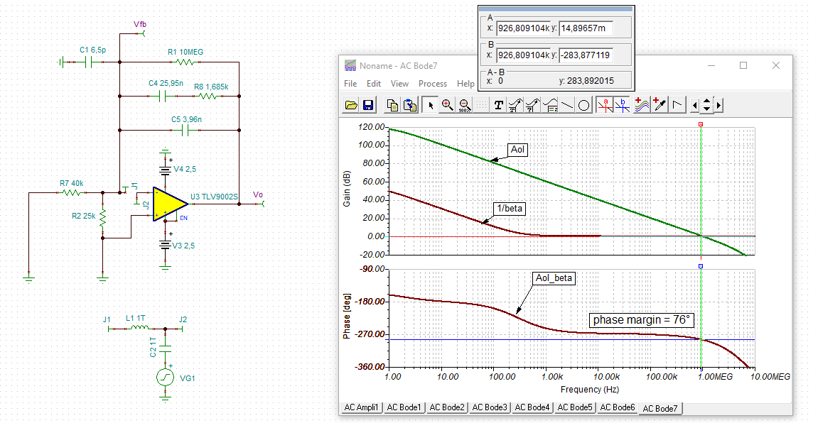
1.) case1. I thought a few reasons why I used the detailed value of 4.53k in. There was a role of phase margin correction. (link:https://e2e.ti.com/blogs_/archives/b/precisionhub/archive/2014/07/15/resistors-in-the-feedback-of-a-buffer-ask-why)

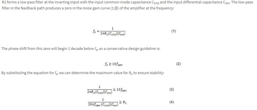
Simulation can determine zero plot according to OP-AMP Common Capacitance, Differential Capacitance, Band width and Feedback resistance.
As a result, it was confirmed that the phase margin was also adjustable.


The question is, the reference voltage is 2.5V DC, but I am wondering if the phase margin value can greatly affect the output value.

2) case1. I think the expression for V_out is as follows.

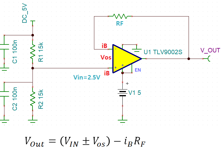
Here, although it is usually V_out ≒ V_ref, it was thought that some output fluctuation may occur due to the offset voltage and bias current characteristics of the OP-AMP.
feedback Resistance is V_ref = 2.5V, I think resistance tuning for accurate output correction. i wonder your opinion.

3). case2. I also think that the output is saturated because it is a DC comparator that outputs high or low by comparing two inputs.
If so, is the DC comparator as above unable to measure gain and phase margin?
If there is a way to measure it, I would appreciate it if you let me know in detail.

 case2_si_comp_1.TSC

 
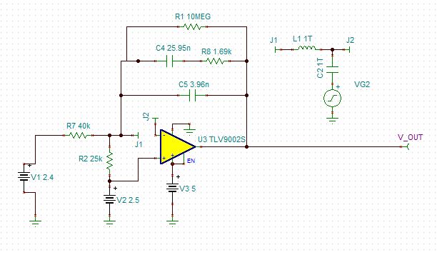
4. )I'm going to show you the integral circuit.

At case2. I think if there is a big difference from the comparator, the feedback R value and the small Feedback cap size.
The attached integral circuit is capable of gain and phase margin simulation. Because the output method is different (integral output and output based on comparison of two inputs), is the integrator capable of margin simulation and comparator impossible? 

7343.DRIVE_OUT_LM358(PhaseGain)_DC.TSC

5. If the DC comparator cannot check the gain and phase margin, is there any way to know the stability and response speed of the circuit?

There are a lot of questions, but I would be grateful if you could answer them.

  • Hi Si Yoon Kim,

    here is the phase stability analysis for the compensator circuit:

    si_comp_phase.TSC

    Kai

  • Dear team,


    Your compensator circuit answer was very helpful.


    I'm really sorry, but can I ask for answers about Question 1),.2).?

    I am very appreciate for your response. Thank you

  • Hi Si Yoon Kim,

    for me this 4.53k resistor is nonsense. I see no reason to install it. It's only effect is to erode the phase margin and cause instability.

    Furthermore, as the TLV9004 is a CMOS OPAmp with ultra low input bias currents, there's absolutely no reason to provide an input bias current cancellation. 5pA x 4.53k = 23nV. So, the input offset voltage of 0.4mV is 17400 times bigger...

    Kai

  • Former Member
    0 Former Member in reply to kai klaas69

    Hi Si Yoon,

    I will address questions 1 and 2 here.

    The phase margin will not affect the output value significantly unless the circuit is unstable or approaching instability.  Otherwise the change in phase margin caused by a resistor in the feedback loop is only an output overshoot during a transient response.  If the circuit has plenty of phase margin, then this really does not matter.

    As for tuning the circuit via this resistor, the bias current of the amplifier is too small for this to make sense, as Kai has pointed out.  Such small changes in the output voltage due to the bias current will be dominated by the offset voltage.

    If you do not know the purpose of the R3 resistor, can it simply be taken out?

    Regards,

    Daniel

  • Dear Team

    Thank you for your reply. Your answers are very helpful for me.

    1). Then, for example, to replace OP-Amp with "LMH6643",
    Power supply based on 5V supply, input bias current = -1.7uA (typ),
    If R = 4.53k, Vos = ± 7mV (max), can it be viewed for the purpose of removing the input bias current?

    lmh6643.pdf

    I am very appreciate for your response. Thank you.

  • Former Member
    0 Former Member

    Hi Si Yoon,

    Regarding question 3, Kai's method is correct.  This is the proper way to simulate phase margin.  You can learn more about it in this presentation.  Note that the purpose of C1 is to model the input impedance of the amplifier and that "Vfb" in his circuit is the node of primary interest as it is equivalent to Aol*Beta.

    For your circuit, you can also perform a slightly more simple analysis to get the phase margin.  It is similar to the method Kai has shown, but you do not need to include the input capacitance of the part as an extra circuit capacitor.  Here is an explanation of the method.

    Regarding questions 4 and 5, before you run a stability analysis on the integrator, you need to ensure there is a proper DC biasing of the circuit.  In other words, you need to make sure that the amplifier is in its linear region of operation and not at one of the two supply rails.  To do this, simply take the circuit and before you run your stability simulation run a DC simulation and check the voltage at the output of the amplifier.  If it is not too close to one of the supply rails, then your circuit has found a biasing point for stability simulation.  If it is too close to a rail, then adjust the DC voltages or circuit component values.

    Regards,

    Daniel

  • Hi Si Yoon Kim,

    the LMH6643 is a HF OPAmp. This is a total different story.

    Kai

  • Dear Team

    Daniel and Kai and TI Team, thank you for your detailed and kindly replies. I learned a lot because of your explanations.
    I wonder One thing, I asked "LMH6643" as an example.
    If it is an HF OPAMP, is it a High Frequency OPAMP?
    Can you tell me what HF OPAMP is in detail?
    What is different from the existing CMOS AMP?
    And, if i replace OP-AMP with "LMH6643" in case1-2, is there a big problem?
    i'm curious about this.

    Thank you very much for your answer.

  • Former Member
    0 Former Member in reply to Si Yoon Kim

    Hi Si Yoon,

    The LMH6643 is a high-speed op amp for systems needing higher bandwidth, such as RF designs.  Designing with these parts can bring different design challenges.  So, I do not recommend them if you do not need the extra bandwidth.

    If you'd like to learn more about these parts, or this one in particular, I recommend you read Bruce Carter's introduction to the topic here in part 1 and part 2.

    Regards,

    Daniel

  • Hi Si Yoon Kim,

    one major difference is that very much lower feedback resistances are used.

    Kai