This thread has been locked.

If you have a related question, please click the "Ask a related question" button in the top right corner. The newly created question will be automatically linked to this question.

LMP8640: The output waveform of the LMP8640

Part Number: LMP8640
Other Parts Discussed in Thread: INA240, INA293

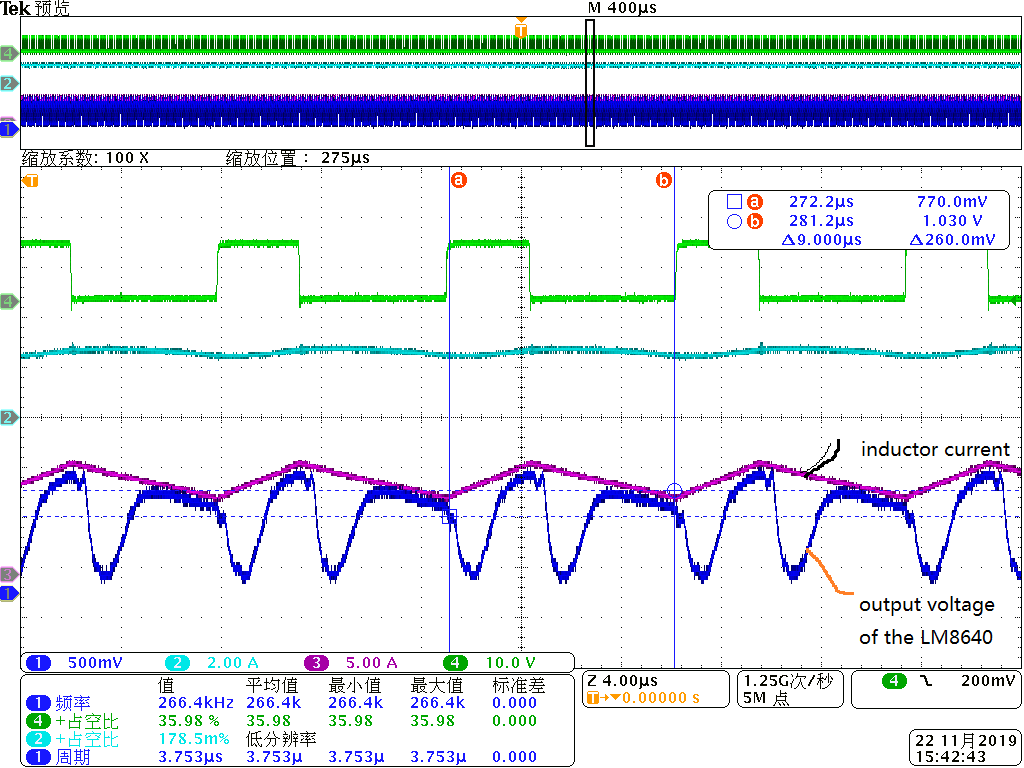
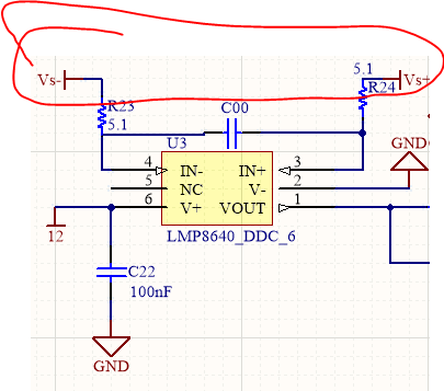
I use the amplifer LMP8640 to sence the inductor current in the Buck converter, I chose the gain as 20, and sense resister 5m. Buck converter : input voltage: 12V; output voltage: 3.3V; output currrent:10A.

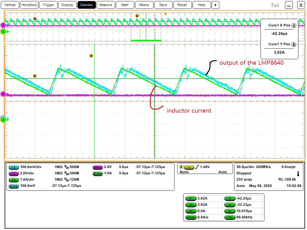
 I found the output waveform of LMP8640 was strange, following is the waveform of the comparision between the inductor waveform and the output waveform of LMP8640? Dose anyone have any clue why there will be a drop in the output waveform when the switch is turned off and on?

 My switch frequency is 100kHz.


  • Hi,

    can you post a schematic?

    Kai

  • Did you know if anyone who has chosen the same amplifer encountered the same problem? Usually , Which parameter of the chip will cause this problem? Is it possible to modify the waveform by modifying some lines of the circuit board?

    Thanks very much!

  • Hello user,

    This could be and AC CMRR issue.  I would look into how much the PGND node changes relative to the GND pin of the LMP8640 device.  If this illustrates some high frequency components then that can explain how the LMP8640 voltage changes as it tries to compensate for the large changes in voltage from the switching.  We have a device, INA240,  that deals with this large transient on the Common mode but has lower bandwidth.

    You may be seeing the common mode voltage change.  This is seen in the datasheet figure 19 and figure 20.  This can be associated with the figure 24 as well.  The magnitude does not have to be that large if the frequency component is high.

  • Hello Javier

    Thanks very much for your reply! 

    I found the bandwidth of the INA240 is 400kHz, is it appropriate for the converter which the switching frequency is 100kHz? I need the accurate inductor current waveform as the control theme is the peak-current control mode.

    By the way, could you provide some other current sense amplifers which may be appropriate ?


    In fact, I also did some other experiments, as illustrated below.

    1>     I short the two input ports of the LMP8640( pin 3 and pin 4, namely in+ and in- ), then I connect it to the either side of the sense resistor. My intention is to see if the output voltage of the LMP8640 will have a undershoot in this case. If there exists undershoot, it illustrates the low CMPP cause the problem. However, the undershoot didn’t show up in the experiment. In addition, the common voltage, namely the voltage of the either side of the sense resistor, dosen’t have a big jump when the switch is turned on and off. The figure 19/20 you mentioned shows the Vcm has a big jump.

     Maybe the common mode step response of the output has a relationship with the oscialliton frequency of the Vcm. But I can’t understand why the undershoot didn’t show up when I short the two input side and connect it to the either side of the sense resistor, if the problem is consisered to be caused by the low AC CMRR.


    2>     I short the GND pin and the In- pin, both are the pin of the LMP8640, and the In- pin is also the negative side of the sense resistor, namely the power GND, the waveform become better, but the undershoot still exists. The waveform is shown below.

  • Hello,

    So in your experiment number 1 there was no change in the output voltage when connection to either side of the resistor?  This also will not be too conclusive as the output is already saturated low when the inputs are subjected to an large CM change.  So if the part wanted to go lower in output it would already be limited by the output voltage.

    The second experiment leads more to a rapid change in CM and a difference in GND potential.  

    The INA293 has larger bandwidth and better CMRR and AC CMRR.  Too bad these have different pin outs and you could not try this one.  At low input voltages the INA293 has lower bandwidth.

  • Hello Javier!

    ‘ At low input voltages the INA293 has lower bandwidth’  that you mentioned,  really reminded me and prompted me to read the datasheet (INA293) more carefully. Thanks very very... much again!

    Yes, when the both input sides were connect the same side of the resistor there was no output change. Maybe  the reason you mentioned is right.

     Output voltage of the amplifer I designed is around 1V,  in this case the bandwidth of the INA293 is still high. As shown below.

     luckily ,  the Pins of the LMP8640 and INA293 are the same.  LMP8640 --SOT-23-6,  INA293--SOT-23-5.  they both have a NC pin.

    Regards!

    NaYan

  • If you have further experimental waveforms about CMRR of the LMP8640, could you load the waveforms under this post?

    Regards

    NaYan

  • NaYan,

    I do not have any other plots for you regarding CMRR, sorry about that.  Also thanks for catching the pin out and they are swap-able.  For some reason I thought he pitch on the pins were different.

    I do believe that the INA293 will behave better but I would not say by how much.  The other item is that the INA293 has a little more headroom on the low side being able to get to -4V for operating conditions.  Also the ABS Max common mode limitation go to -20V instead of -6V. 

  • Thank you very much for the additional information of the INA293.
    After replacing LMP8640 with the INA293, I will update the waveform in this post.

    Regards!