A related question is a question created from another question. When the related question is created, it will be automatically linked to the original question.
If you have a related question, please click the "Ask a related question" button in the top right corner. The newly created question will be automatically linked to this question.
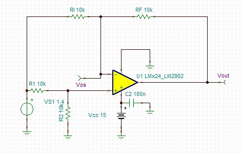
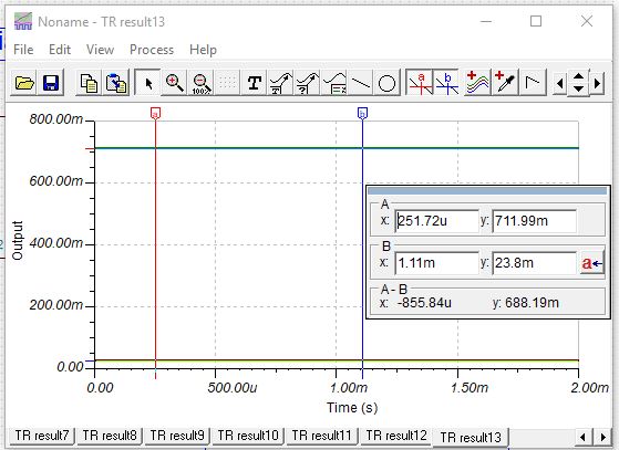
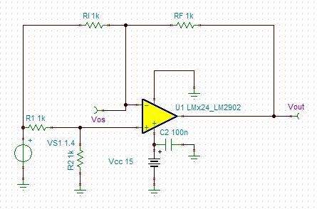
The output must be able to sink the current from the inverting feedback. With both input sides at 1.4V , the ideal output would be 0V. With 10k resistors, the feedback current is 1.4V/20k = 70uA . The model supports this sink current at low voltage, however most LM2902 will need to use the second sink driver, a PNP follower, so output will be near 600mV. With 1k resistors, things get worse; now sink current is 700uA so an output near 0.7V is certain. See figure 1 in data sheet, output sinking characteristics. Also see application note section 3.1 , Design Guidelines for Devices with LM324/LM358 Cores
Try 100k resistors, that is only 7uA sink current.