Other Parts Discussed in Thread: LM317
Hello,
I have only one issue i don't no the reason of it, i am connecting the leds with the led driver, the led driver is supplied by a 5 volts voltage regulator "LT323A" ,the 12 volts over the leds, then a 2 channels analog multiplier "max337" then to the instrumental amplifier "INA118", the amplifiers is working as expected when i supply it with another 12 volt supply but to connected to the sam 12 volts rail it doesn't give the right expected value.
I have tried different things like supplying the amplifier with a separated 5 volt voltage regulator, i have changed the main 5volt regulator by "LM317" adjustable regulator but its not working with the same 12volts of the circuit.
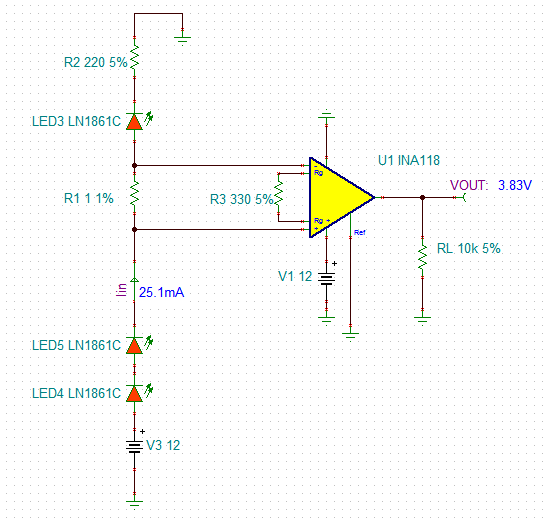
I took it step backward and I made one branch as a basic circuit without using a led driver and i didn't get the right result from the amplifier (12v, 3 leds series, 660ohms resistor to set the current 18 mAmp).
i uploaded the schematic
thanks for you help and regards.