This thread has been locked.

If you have a related question, please click the "Ask a related question" button in the top right corner. The newly created question will be automatically linked to this question.

OPA2192: OPA2192 Magnification difference

Part Number: OPA2192
Other Parts Discussed in Thread: OPA192,

Hi Support team 


The current magnification is 681K // 2K. Considering that the magnification needs to be the same, it must be changed to 68.1K // 0.2K. Is there any problem with the use of IC?

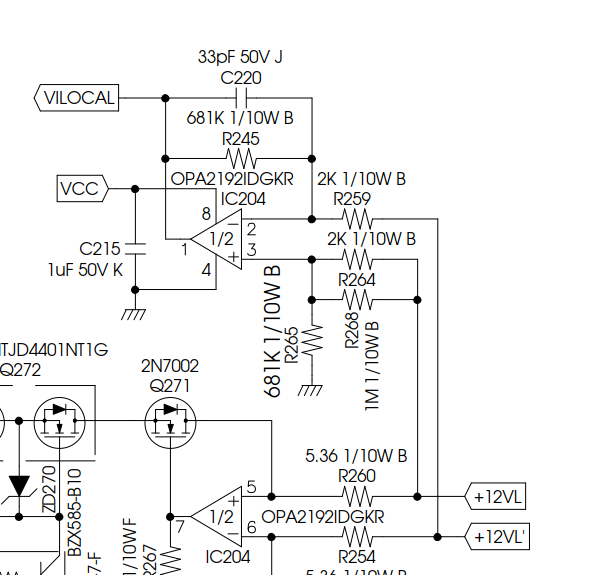
Application circuit is as following 

  • Hi Red,

    What is Vcc in this circuit? I assumed that this is a working circuit and you just wanted to change the resistor values and maintain the OPA192's gain. If you do, you need to change both V- and V+ inputs. What are the signal amplitude from +12VL and +12VL' terminals?

    Best,

    Raymond

  • Hi Raymond, 

    Vcc now provides 18V, +12VL and +12VL’ are connected in series with Rsense 68.18uohm to detect the output current.
    So if the OPA gain remains the same, what will be the problem with IC like 681K // 2K & 68.1K // 0.2K?? I still want to know.
    The output current is 196.72A at full load.

  • Hi Red,

    R259 and R264 limit the current into the input pins of OPA2192 to about 6mA, if the 12V across the shunt is present before the OPA2192 is powered. Decreasing the resistors would ruin this protection.

    Why do you want to decrease the resistors at all?

    Kai

  • Hi Red,

    I agreed with Kai. With 681K // 2K gain setting, the input is limited to 6mA, when there is no current flow through the shunt. With 68.1K // 0.2K, the input current is increased to 60mA under the same scenario. The voltage across the shunt  is 196.72A*68.18uOhm = 13.4mV is not an issue, when the max. current is flowing through the shunt. The input pins' current should be limited within +/-10mA or lower.

    Best,

    Raymond

  • Hi Kai, Raymond, 

    thanks for your reply 

    reply your question, For the same OPA Gain, the resistance becomes smaller the slope of the OPA output voltage rise will become faster, that why my customer considers to reduce the resistor, 

    few questions

    1. OPA is before powered, so will the input pin be connected to ground? Otherwise how to have 12V/0.2K= 60mA?

    2. If customer wants to meet the input pin to meet the +/-10mA or lower requirements,

    then there is a test condition in the customer specifications. When the output current is 140% load for an instant, the alert signal should be changed within 55us. Because of transition depends on OPA output voltage to make a judgment, then what volume can match the input resistance,

    The resistance matching causes the output voltage slope to be different.

  • Hi Red,

    1. OPA is before powered, so will the input pin be connected to ground? Otherwise how to have 12V/0.2K= 60mA?

    It is likely that the OPA192's ground is isolated from input pin without DC power. When datasheet is specifying the absolute max. ratings, it means that the part will get damaged if the recommendation is violet, and no warranty will be provided. Without looking at the actual IC schematic, I can not be sure but speculate the possibilities. For instance, when the IC is powering up with 12V sitting at the input; specific transient conditions occurred at the input; power transients at the supply pins; input protection under transient condition at the input etc. (OPA192 does not use input protection diodes at the input protection circuitry, see p.24 of the datasheet). In other words, input current limits are required to protect the IC and not exceeding +/-10mA at the input pins as stated.  

    2. If customer wants to meet the input pin to meet the +/-10mA or lower requirements,

    I have to ask the IC's designer, if you are interested to have the answer. There is no time specification associated with these absolute max. ratings. Without these time figures, I would not recommend to exceed or equal to the ratings. 

    3. The resistance matching causes the output voltage slope to be different.

    What is the real issues? 

    Based on 33pF and 681kOhm in IC204, the BW of the OPA192 is limited. In other words, the output voltage at IC204 is not responding to the current changes at the input, especially within 55usec. To have this particular requirements, the BW of OPA192 will need >20kHz (minimum) to response. 

    Best,

    Raymond

  • Hi Raymond, 

    thanks a lot for reply, 

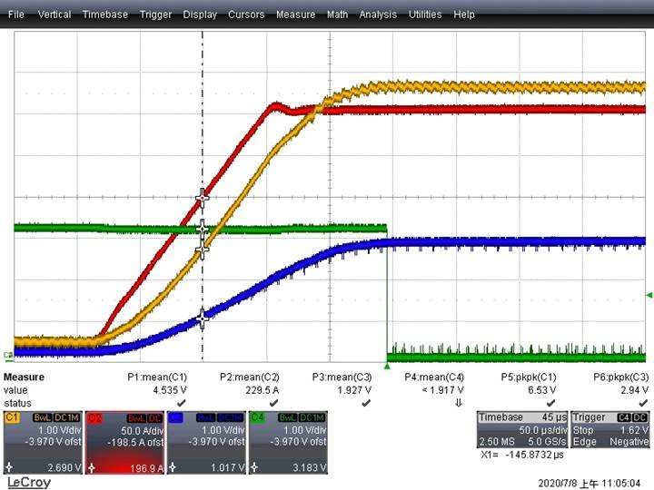
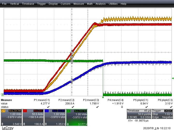
     my customer start to load 20A and then load to 300A, and then measure whether 196.72A corresponds to the same Vilocal voltage
    The first picture is 681K/2K, the second picture is 68.1K/0.2K. It is obvious that the two pictures have different voltages at the same current Vilocal.

    are you able to explain the theory of those two waveforms

    CH1_Vilocal CH2_Iout CH3_Vilocal’ CH4 alert.

     681K / 2K

    68.1K/0.2K

  • Hi Red,

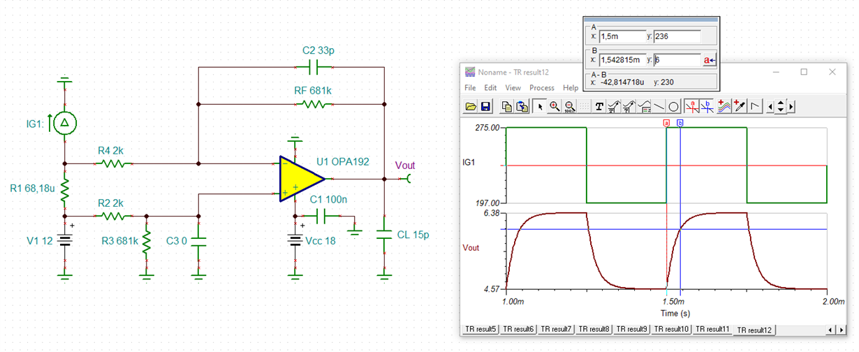
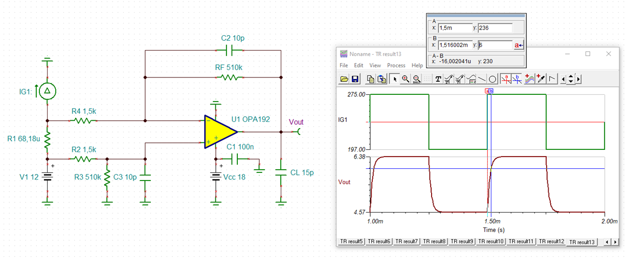
    this is what you have right now:

    And this is what I would recommend:

    red_opa2192.TSC

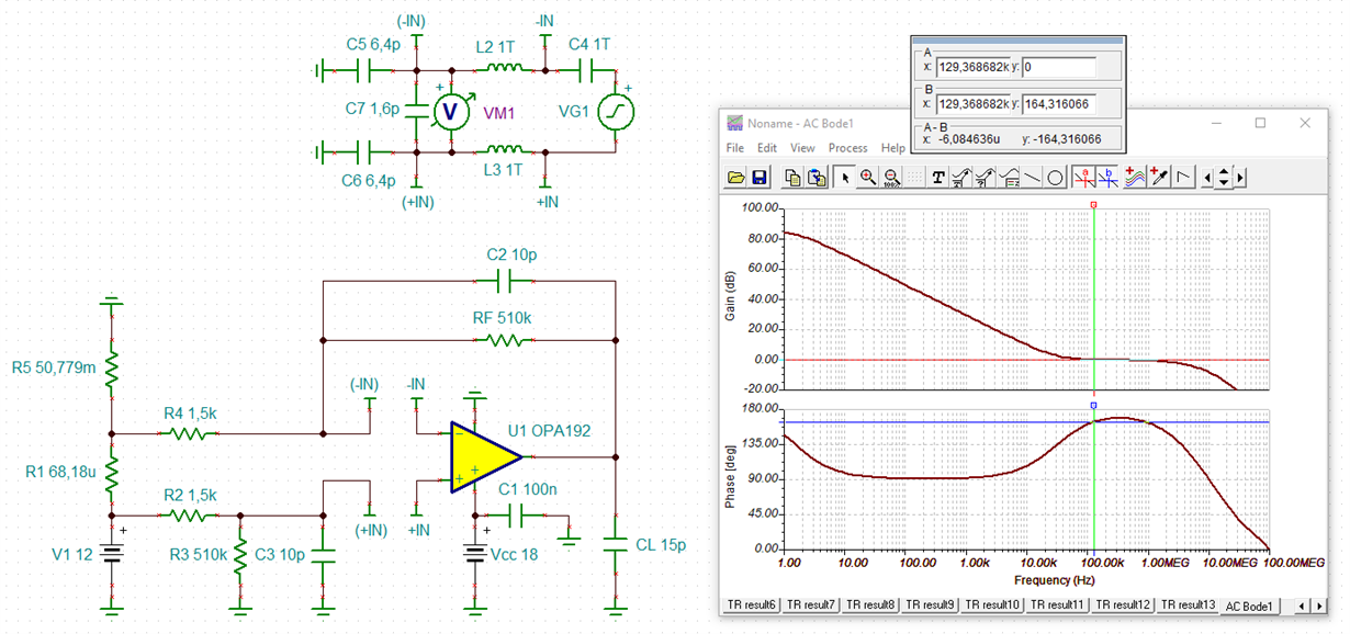
    The phase stability analysis shows that this modification would be stable:

    red_opa2192_1.TSC

    By the way, even if the supply voltage of OPA2192 goes up before the +12V supply comes up, there are good reasons to limit the input current of OPAmp: It prevents damage, if you slip off with the probe and short circuit the supply voltage of OPAmp and it limits the current when the +12V supply has short overvoltage spikes (inductive kick backs, etc.). So it's good design practise to have a current limiting.

    Kai

  • Hi Kai,

    Thanks for the simulation, demonstration, and help out in answering questions via E2E inquiries. 

    Hi Red,

    Kai has answered your questions. Please let us know if you need further assistant. 

    Best,

    Raymond