This thread has been locked.

If you have a related question, please click the "Ask a related question" button in the top right corner. The newly created question will be automatically linked to this question.

OPA4314: Input Voltage Noise inconsistency

Part Number: OPA4314
Other Parts Discussed in Thread: OPA827, TLV9062, OPA388, OPA837, OPA4196, OPA4191, TLC2264, TLV2264

Hi,

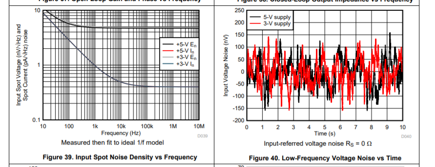
why is the input voltage noise (f=0.1Hz to 10Hz) specified with 5µVpp while the oscillogram shows only about 1.5µVpp? Which value is correct?
I need this low second value (VS=+5V).

Thanks,
Torsten

  • Morning Kitong, 

    When I run this calculation based on +/-2.75 supply spot noise, I get an expected 1.5uVpp 0.1Hz to10Hz noise - kind of matching figure 11 in the datasheet.  That 5uV spec table number might be in error. From the right curve here I estimate 13nV flatband with 80Hz 1/f corner. 

    Using this equation, you can get an equivalent flat noise that will integrate to the same power as the actual 1/f shape. This is completely general, but using F1=0.1Hz and F2=10Hz with an 80Hz 1/f corner and flatband number of 13nv gives 81nV. 

    THe next step is to take this times the square root of the noise power bandwidth or root(10Hz-0.1Hz) to get 0.25uVrms.Then, normally we take that times a 6X crest facter to get 1.5uV pp. Keep in mind, every sweep of Figure 11 will give slightly different results. Also, there is a lot of part to part variation on 1/f corner - that is described in an article I can't find right now. 

  • Former Member
    0 Former Member

    Hi Torsten,

    Thanks for your question.  I know you've marked it as resolved, but I wanted to dig into this a bit more.  I quickly estimated the total noise due to 1/f noise using a different formula than Michael (see TI Precision Labs) and got a higher value of 4uVpp.  I am not implying that Michael is wrong, but that a different method may have been used to calculate the expected noise by the design team.  There is also broadband noise to consider, though it may be insignificant in this region.

    I also reached out to the development team to see if they could provide an explanation on their end.  They got back very quickly and below is a paraphrased summary of the reply.

    The time domain data can be somewhat misleading.  Why?  Because there can be device to device variation, such that the device chosen for the time domain plot may actually have better than average performance.  More importantly, the 4 to 5uVpp value is really something of a worst case value.  In other words, you're unlikely to see it in a random 10 second sample and are more likely to see a lower peak-to-peak value.  You would probably have to sit around for a while to actually capture a shot of this much noise.  In the future, this may be considered when taking data for the data sheet so as to avoid confusion.  Lastly, it was suggested to consider the typical specification rather than the time domain data because the typical spec should give you a better average across device variation.

    Hopefully this helps.

    Regards,

    Daniel

  • Hi,

    other datasheets (TLV9062, OPA827, e.g.) show a much better match between the time domain plot and the typical specification in the table. So I think it's either just the wrong curve or a typo in the table.

    Which value to choose? The worse one :-) No, all jokes aside, the value of the table. It's more important and relevant than a curve in a figure.

    Kai

  • Former Member
    0 Former Member in reply to kai klaas69

    Hi Kai,

    Thanks for pointing this out and providing examples.  I have passed them along to the appropriate engineer for future reference.  I'm not sure whether this data will be re-taken, but either way the specification in the table is what matters as you have stated.

    Regards,

    Daniel

  • Actually, there is quite a bit of info out there on this topic. The equation and approach I showed has been validated over 30+ years. 

    I recently published an updated noise preamp using the OPA388 to take the that 0.1Hz to 10Hz 10second sweep in an Audio Express article (July 2020 issue) - that is basically an upgrade over this really good article by Art Kay. 

    http://www.ti.com/lit/ug/slau522/slau522.pdf

    The equation is developed in 3 lines (equation 13 to15) on page 7 here, Completely general and exactly correct if the noise follows a 1/f profile. I originally developed these circa 1990 for the Comlinear CFA parts. This equation is approx in that not all parts show a true 1/f noise profile. 

    http://www.ti.com/lit/an/sboa066a/sboa066a.pdf

    I tend to rely on the measured plots of spot noise and that 10sec noise sweep - which is using that gain of 100 active filter ckt in Art's article, so nicely bandlimited. 

    The typ spec is probably an error since the measured 10sec sweep is quite a bit lower - and that sweep matches up with what I would expect from the spot noise plot. It is possible they remeasured an egregiously bad unit to generate that 5uVpp,  but that does not lead to much confidence in the spec. And I doubt it, the measured 10sec sweep should have linked up to that typ spec - they just missed it.

  • Lets go through another recent example I had a lot to do with, here are the OPA837 noise specs 

    We even have a typ 1/f corner here - note the datasheet spot noise plot are fitted to a 1/f model from actual data that might not match that shape perfectly. 

    (the next few Audio Express articles are stepping through how we actually get those input spot noise curves - starting with the latest and greatest noise preamp). 

    So applying this equation with those numbers for a 0.1Hz to 10Hz span, 

    This would predict an equivalent flat spot noise of 20.4nV/rootHz

    Then to get an RMS in that span, time root(9.9Hz) gives 64uVrms

    Then to get Vpp (for that 10sec sweep using the gain of 100 active filter preamp) that would predict a 385uVpp

    Lets look at the datasheet measured results. looks like about 320uVpp on this sweep - just didn't see that 6sig excursion here, but the intent of the calculation is to give a reasonable boundary, and the data is slightly within that. This is what I mean by validated. 

  • Former Member
    0 Former Member in reply to Michael Steffes

    Hi Michael,

    Thanks for the input here.  I spent some time going through the content you've suggested and found it quite helpful.

    I've also gone back and re-done the calculation using Art's formula.  I realized that, when using the bandwidth of the amplifier and assuming a factor of 1.57 for the single-order brickwall filter approximation, I'd get a value of 4uVpp.  Using a cutoff of 10Hz however, I got 2uVpp, which is at least closer to your result.  I used the +/-2.75V supply curve to estimate the noise density at 10Hz.

    Taking another look at figure 12 in the datasheet, I'm not sure that we really have a true 1/f region.  It looks less than ideal to me.  But then again, if we're only measuring from 0.1Hz to 10Hz I'd think it would not matter based on the fact that the knee of the curve seems to come in much later...

    I've brought this up again with the systems engineer, but they have simulation data that corroborates their table spec.  I may try to get a third opinion within the team.

    Regards,

    Daniel

  • Really, you are not using a single pole filter for the time domain plot, so the 1.57X is an obvious error.

    The original question was hoping the 5uVpp was an error, I think it is and the plots are more believable with 1.5uVpp since the "measured" spot noise maps to the "measured 10sec Vpp noise (with that .1Hz to 10Hz filter I am sure they are using)  very nicely. Your systems folks can keep working to prove the 5uVpp correct, but perhaps lose the design - really? 

    Kai, in this case, I would believe the plots over a typ spec probably calculated using a mistaken flow.Measured data trumps typ numbers pulled out of free space every time. I used to spend a lot of time making sure the spec lines correlated with the char curves - takes a lot of time, and this seems like a miss.

  • Oh incidentally Daniel, if they have design sim data showing 5uVpp is correct, then the spot noise must tilt up a lot more going below the shown span. But the then the 10sec sweep looks wrong then? 

  • Former Member
    0 Former Member

    Hello Torsten,

    While this point is being investigated, it is worth pointing out that the noise specification is only a typical specification.  In other words, your part is not guaranteed to have this performance.  If you really need this performance, you may have to pick a part with a significantly lower noise specification to give yourself ample margin as I'm not sure that this is a performance specification that is ever guaranteed.

    Do you have the ability to screen for this noise specification?

    I am happy to find a more suitable alternative part for your system if you are willing to consider it and know which specifications, other than this noise value, are most important.

    Regards,

    Daniel

  • Former Member
    0 Former Member in reply to Michael Steffes

    Hi Michael,

    I understand your arguments and thank you for providing your viewpoint on this matter.  The wheels are spinning internally to have more people take a look at this.  I will look to provide an update when I have new information.

    In the meantime, I will try to help Torsten find a different solution.  If a 3x factor on a typical noise spec is that critical, then more design margin may be needed anyway.  Just my opinion.

    Regards,

    Daniel 

  • You bet Daniel, 

    There are PA parts that match the analysis I have presented here exactly - I recently used the OPA827 as a vehicle in that July 2020 article on low frequency and popcorn noise in Audio Express. Here is that excerpt, everything matches up nicely from the datasheet, TINA sim, to 0.1Hz to 10Hz Vpp results. (this is a subscription magazine, so I can't insert a link). 

    Low Frequency and Popcorn Noise in High Speed Amplifiers article excerpt.docx

  • Hi Daniel,
    yes, gladly I send to you the other requirements:
    - Noise voltage 4µVpp max. at fB = 0.5Hz to 50Hz
    - Single supply voltage: 5V
    - Supply current per amplifier: 200µA max.
    Looking forward to your recommendations.
    Torsten

  • Hi Torsten,

    you could use the OPA4191 or the OPA4196. But the low noise is only valid for the limited common mode input voltage range -0.1V...2V.

    Kai

  • Former Member
    0 Former Member in reply to Kitong-H

    Hi Torsten,

    Another suggestion would be to look at the TLC2264/TLV2264.  The quiescent current may be on the borderline.  But, otherwise I think it may be worth a look.  The TLC2264 is especially cost effective.

    Regards,

    Daniel

  • Former Member
    0 Former Member in reply to Kitong-H

    Hello Torsten,

    Please let me know if the advised parts are acceptable.  If I do not hear back from you after some time, I will assume that you have taken one of these suggestions to be acceptable and will mark the thread as resolved.

    Also, feel free to return with a follow up question.

    Regards,

    Daniel

  • Hi Daniel,
    the TLC2264 might be usable, possibly the OPA4196 too, provided my supply current amount will be sufficient - I will know this when I will have completed the component selection of my project, so you can mark this thread as resolved. Thanks to all
    Torsten

  • Good luck :-)

    Kai