


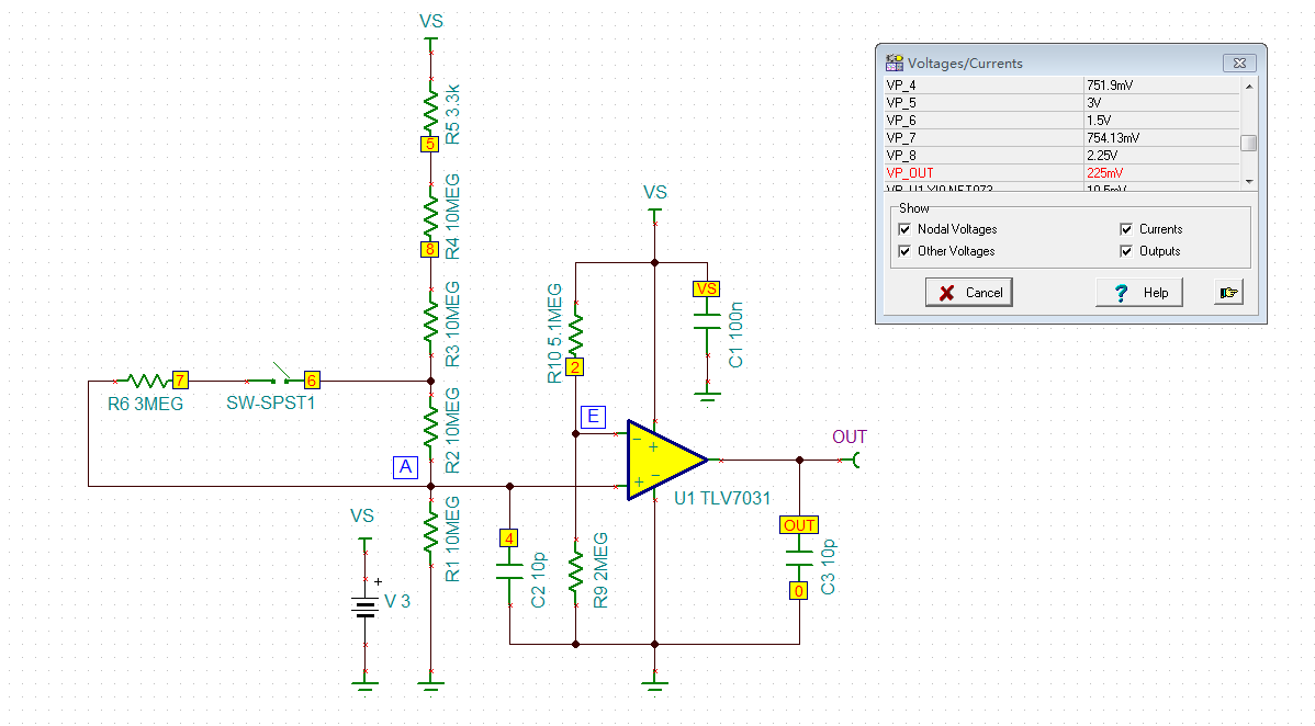
I use Tina for simulation experiment,and output is correct。
But the output in the actual circuit is wrong。Is the external resistance too high?
I use Tina for simulation experiment,and output is correct。
But the output in the actual circuit is wrong。Is the external resistance too high?


