This thread has been locked.

If you have a related question, please click the "Ask a related question" button in the top right corner. The newly created question will be automatically linked to this question.

TLC2252: TLC2252 Filter design Tool

Part Number: TLC2252
Other Parts Discussed in Thread: TINA-TI, OPA320, OPA325, AFE031

Dear Sir, good day! 

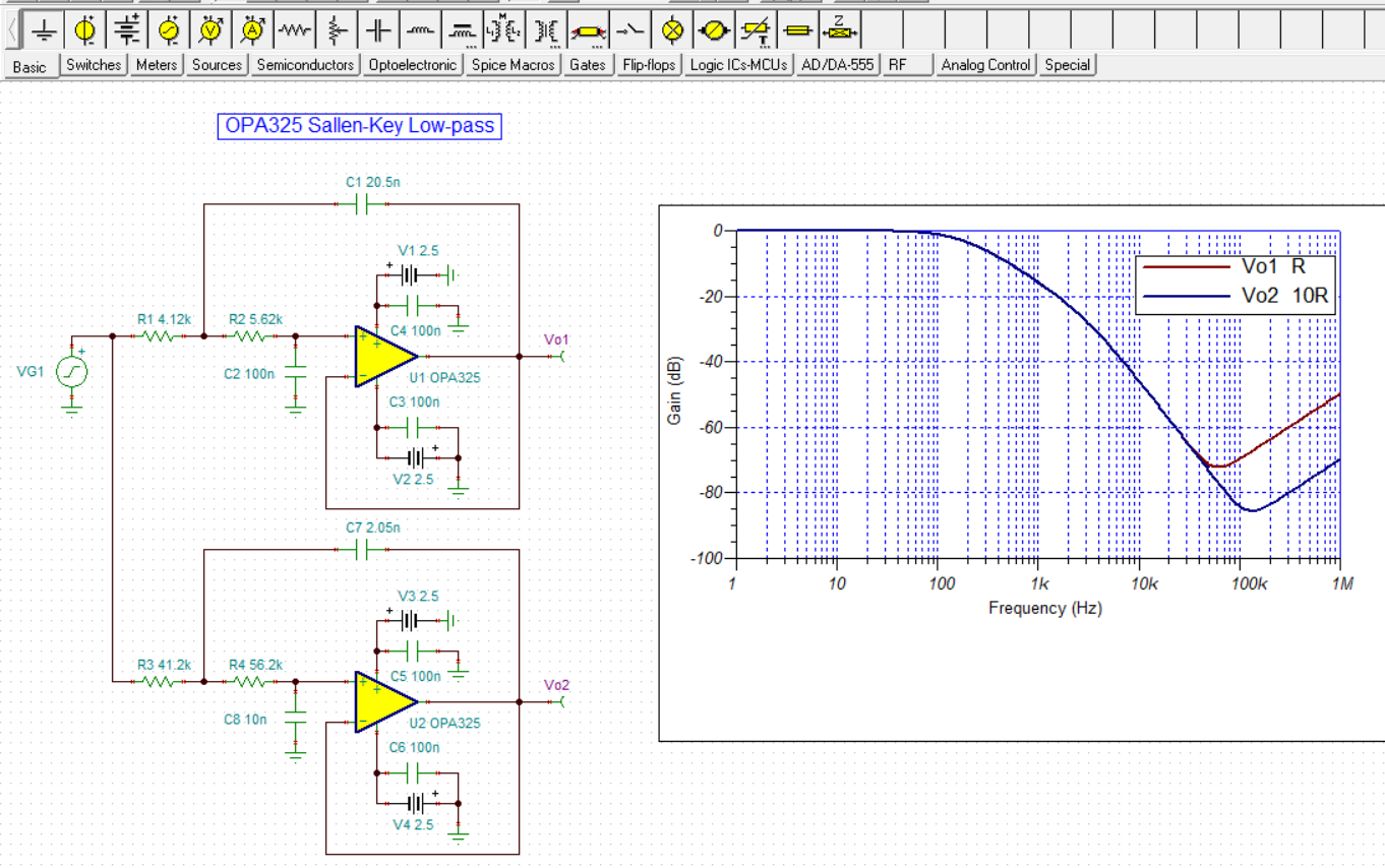
I made calculation for low-pass filter. Please, see attach. 

The Filter Design Tool program suggested amplifier TLC2252. But it doesn't matter. The circuit has 10 nF and 20.5 nF capacitors. But these are inconvenient values. Does the program allow to change the capacitor values? 

TIA

Sincerely,

Vladimir Naumenkov

filter-design-report-2300Hz.pdf

  • Hi Vladimir,

    the TLC2255 is a very low power OPAmp and doesn't like very much low impedant Sallen-Key filters. See the erosion of frequency response at high frequencies:

    So one remedy is to choose higher impedant feedback components:

    A filter using more convenient components could look like this:

    Or this:

    Furtherly increasing the impedances will furtherly improve the high frequency behaviour:

    vladimir_tlc2252.TSC

    Kai

  • Dear Kai, thank you!

    Please, report, what program you use for filter calculation? So that I can change the value of the capacitors for a convenient value.

    TIA

    Vladimir Naumenkov

  • Hi Vladimir,

    I use my head :-)

    The simulation is done by the help of TINA-TI.

    Kai

  • Hi Kai,

    Thanks for the explanation and simulation. 

    Hi Vladimir, 

    If you need further assistant, please let us know.

    Best,

    Raymond

  • Hi Vladimir,

    The gain fold-back that Kai reports for the Sallen Key (SK) low-pass is primarily the result of the op amp's decreasing open-loop gain (Aol), and increasing open-loop output impedance (Zo) as the frequency increases. The fold-back characteristic tends to be more pronounced with very low operating current (Iq) op amps such as the TLC2252, because they often exhibit low bandwidth and higher, sometimes complex, Zo across frequency. The fold-back often can be pushed out to a higher frequency by using a higher bandwidth op amp which typically has lower Zol, but at the expense of higher Iq. Additionally, scaling the resistors and capacitors as Kai has recommended improve's the SK's filter responses so that is an easy improvement.

    If your circuit can tolerate somewhat higher Iq, TI has modern op amps that feature wide bandwidth, low noise, and low Zo across frequency - all of which will improve the Sallen-Key's low-pass response vs frequency. For example, the OPA320 and lower current OPA325 are two modern 5 V CMOS op amps I would recommend. I re-simulated your Sallen Key low-pass with the OPA325 in place of the TLC2252 and the response improvement is evident from the graph shown below. Additionally, I included the case where the resistors were scaled up by 10x, and the capacitors down by 10x, in the simulation.

    The fold-back with the OPA325 doesn't occur until about 61.7 kHz, with an attenuation of -72 dB for the 1x components. The fold-back frequency increases to about 135 kHz, with an attenuation of -85.5 dB for the 10x components. I expect this would be even more improved with the higher current OPA320 which has wider bandwidth and even lower and flatter Zo across frequency.

    Do note that the Multiple Feedback (MFB) exhibits better fold-back behavior than the Sallen Key. If you need to stay with a low current op amp such as the TLC2252 there is response improvement from the MFB. And if your need higher supply voltages there are many op amps that will fill this role.

    Regards, Thomas

    Precision Amplifiers Applications Engineering

    OPA325_SK_LP_01.TSC

  • Dear Tamara, dear Kai, dear Raymond, dear Thomas!

    Thank you.

    In fact, everything is somewhat more complicated. 

    I need a band-pass filter at 1873 Hz. I calculated manually an MFB filter at a -3dB band 200Hz. This is a “MFB filter 1” circuit. I need to receive a signal with phase manipulation (phase-shift keying signal - BPSK). I drew a circuit in TINA-TI, that generates BPSK signal, please, see attachs. I set the size of a Filter 1 quality Q= 10.

    The signal after the filter 1 had the form: after phase change some time undesirable oscillatory process took place. It stirs to normal work of the receiver - we cannot correctly define the moment of change of a phase. This can be clearly seen if you look at the output signal with an oscilloscope.

    Then, I have changed parameters of the filter, I have increased considerably a pass-band (approximately to 1500 Hz and even more) and have set filter quality Q = 1, please see “MFB filter 2” circuit. Then, process of change of a phase began to occur no unwanted generation. Such form of a signal suits us, but here the filter 2 already ceases to be the normal filter!  So I tried to connect low-pass filter and high-pass filter in series.  Please see "Low-pass 2200 plus high-pass 1300.TSC". With such a filter, there is also no unwanted generation at the time of the phase change, but the bandwidth of such a filter is also large.

    QUESTION: Whether it is possible to avoid long oscillatory process at the moment of change of a phase and thus not to increase strongly pass-band of the filter? 

    TIA

    Sincerely

    Vladimir Naumenkov

    Minsk, Belarus

    Low-pass 2200 plus high-pass 1300.TSCLow-pass 2200 plus high-pass 1300_BPSK.TSCMFB filter 1_BPSK.TSCMFB filter 2_BPSK.TSCMFB_Filter 1.TSCMFB_Filter 2.TSC

  • Hello Vladimir,

    Narrow band band-pass filters are often synthesized with the SK or MFB band-pass typologies; especially, when the circuit has a relatively high Q as you first mention where the Q is 10. However, when the Q is very low such as a Q=1, then the band-pass filter is commonly synthesized using cascaded low-pass and high-pass filters, as you have done in the TINA schematic. The phase shift behavior through the filter is a function of the band-pass Q, and the type of filter response it is designed for such as Butterworth, Chebychev, Bessel, etc. Each filter response type has its own unique amplitude, phase and delay characteristics. Typically, the more aggressive the stop-band attenuation near cutoff, the more radical the phase change occurring in that frequency range. 

    The Bessel and Gaussian response filters have much more linear phase change vs frequency characteristics than the Butterworth and Chebychev. Therefore, when you synthesize an active filter be it a band-pass typology, or a low-pass/high-pass topology, try using one of the linear phase response options. You may find that a compromise can be found that satisfies both the band-pass bandwidth and phase change that you require for your application.

    Nice picture of the kids having fun!

    Regards, Thomas

    Precision Amplifiers Applications Engineering

  • Dear Thomas, thank you.

    That's what I still can't understand. Take the circuit "MFB Filter 2", please see attach. On the oscilloscope in TINA, you can see that the output signal is AHEAD of the input signal. How can this be? I even simulated the circuit in LTspice and it's the same there! Please, see "Figure 1" - the blue trace is the out signal. In the range from 0 to 0.7 ms, this is clearly visible. Or does it just seem so? 

    Sincerely,

    Vladimir Naumenkov

    Minsk, Belarus

    3482.Figure 1.docx

    7875.MFB filter 2_BPSK.TSC

  • Hi Vladimir,

    what do you need the bandpass for? Can you explain your demodulation scheme in detail?

    Kai

  • Hey Tom, your filters are quite a bit lower cutoff than intended - the higher R one will be much higher spot noise once you correct the cutoff.

    You guys are calling this effect foldback? It is more commonly called a loss of stopband rejection - as the closed loop Zout of the op amp comes up with frequency, the input signal feeds straight through the feedback cap and shows up more and more going to higher F. And yes, the MFB does not have this issue. Going for a BP filter, why not the DABP? 

  • Dear Kai, thank you.

    Night has already come for us. I will describe in more detail tomorrow.

    Sincerely,

    Vladimir Naumenkov

    www.agat.by

    Minsk, Belarus

  • Dear Michael, thank you

    I remember all the time about the filter, that you sent me earlier. Nice filter, but many elements. 

    Sincerely,

    Vladimir Naumenkov

  • Dear Micharl, thank you

    Sincerely,

    Vladimir Naumenkov

  • Dear Kai, thank you

    We need to receive BPSK signal from two-wire line. Line length up to 5 km. There is a signal matching transformer at the input, and then a bandpass filter for a 1873 Hz. The signal amplitude at the transformer’s input can be from 50 mV to 1 V. If the signal is 1 V, then the filter is not needed, but, if there is 50 mV, then it will be needed! What should be the bandwidth? Good question. Well, so that I can remove the interference (that will gather in the line) as much as possible. The "narrower" the better, within reasonable limits.  Initially I calculated a two-stage MFB filter for a 200 Hz bandwidth.  This is "Filter 1". At the time of the phase change, an oscillatory process took place, which is unacceptable, please see “Figure 2”. After the filter, the signal is fed to the automatic gain control circuit (please, see “Circuit AGC-2”. The output of AGC circuit is maintained at 1 V. DA17 amplifier and DD6 form a logical signal, that is fed to the microcontroller. A reference frequency of 1873 Hz is also fed to the microcontroller. Circuit works badly with “Filter 1”. With “Filter 2” – ok. The output of “filter 2” is shown in “Figure 1”. But with a line of 5 km, there was no way to check. That is, how the circuit works under conditions of a small signal at the input and in the presence of interference, we do not know yet.

    II made marks 1 and 2 on the oscillogram "Figure 1_Filter 2_2000 Hz".  What do you think - do these elements on the upper and lower oscillograms correspond to each other?

    Please, see atach

    TIA

    Sincerely

    Vladimir Naumenkov

    4075.MFB filter 2_2000 Hz band_BPSK.TSC

    7343.MFB filter 1_200 Hz band_BPSK.TSC

    6330.Circuit_ AGC_2.docx

    0083.Figure 2.docx

    Figure 1__Filter 2__2000 Hz.docx

  • Hi Vladimir,

    the frequency band of BPSK signal is said to be

    fc-1/Tb...fc+1/Tb

    where fc is the frequency of carrier and Tb is the bit length of data to be transmitted. In your simulation fc = 1.8kHz and Tb is 4.44ms. This results in a frequency band of

    1575Hz...2025Hz.

    So your bandpass filter should better have a bandwidth of 450Hz?

    Kai

  • Dear Kai, have a good day!

    Thank you

    "bandpass filter should better have a bandwidth of 450Hz?"

    Yes, I wanted something like that, but I still can't!

    Please, see also attachs, that a sent to Michael Steffes.

    TIA

    Sincerely,

    Vladimir Naumenkov

    Minsk_Belarus

    6813.3527.4th order DABP with OPA1678 working_BPSK.TSC6740.Figure 3.docx

  • Dear Michael

    I feed BPSK signal at your filter. Please, see attachs

    TIA

    Sincerely

    Vladimir Naumenkov

    Minsk

    3527.4th order DABP with OPA1678 working_BPSK.TSCFigure 3.docx

  • Hi Vladimir,

    maybe I would do it this way:

    A passive bandpass has a more linear phase response than an active one.

    vladimir_tlv170.TSC

    Kai

  • Dear Kai!

    Thank you!

    Sincerely,

    Vladimir Naumenkov

    Minsk_Belarus 

  • Hi Vladimir,

    Here is another passive filter reference. This is how powerline communication uses in the application with 4th order passive BPF, which is typically done at much higher frequency. At lower filtering frequency, the filter circuit may not have significant advantages. 

    https://www.ti.com/lit/ds/symlink/afe031.pdf?ts=1598380651211&ref_url=https%253A%252F%252Fwww.ti.com%252Fproduct%252FAFE031

    Enclosed is a simulation for the BPF. 

    /cfs-file/__key/communityserver-discussions-components-files/14/4th-order-Band-Pass-Filter-01242020.TSC

    Best,

    Raymond

  • Dear Raymond, thank you.                                                                                                                                  

    Please, answer.

    In your example in TINA:

    R1=1.3k, R2=10k

    Then, I guess, you made filter for about 0-dB passband attenuation?

    In AFE031 datasheet, page 29: 

    C1= 1 / 6.28 * F1 * Zc  (1) , 

    C2=  1 / 6.28 * F2 * Zc (2),

    L1= Zc / 6.28 * F2       (3),

    L2= Zc / 6.28 * F1       (4).

    QUESTIONS:   1)  in (1), (2), (3), (4) :  Zc= R1 = 1.3k ?

                              2) F1 and F2 - are cutoff frequencies?  If I need filter at 1870Hz, then I can set F1= 1600 Hz, F2= 2000 Hz?

    TIA

    Sincerely,

    Vladimir Naumenkov

    www.agat.by  

  • Hi Vladmir,

    The 4th order bandpass filter is not going to be as precise as the active filter, since the tolerances of LC are fairly large from off the shelf components, unless you are willing to fine tune the values on your own for a given frequency. 

    Typically, I use the equations on p.29 to approx. BPF region, then I am altering the damping resistor value to remove Q and narrow the BW down to my design specification. For your filter design requirements, f1=1575Hz, f2=2025Hz, the filter characteristic impedance is approx. sqrt(L1/C2)=sqrt(1.5mH/1.5nf)=1kOhm (you can change to what your application is called out). 

    For your filter design, C1 = 101nf,  C2 = 78.6nf, L1 = 77.6mH and L2 = 101.1mH, the capacitor C on the right side of Figure 32 is used to match the impedance of the Rx receiver. Here is what I got after I enter above values into the simulation. 

    Once the filter is close to what you'd like, you can start to play around simulation and refine LCR parameters to meet the design requirements.  

    Enclosed is the simulation of the above filter. 

    /cfs-file/__key/communityserver-discussions-components-files/14/4th-order-Band-Pass-Filter-08262020.TSC

    If you have any questions, please let us know. 

    Best,

    Raymond

  • This is another filter that could be used:

    vladimir_tlv170_1.TSC

    What filter can be used also depends on the demodulation scheme :-)

    Kai

  • Dear Raymond, thank you

    Sincerely,

    Vladimir Naumenkov

    Minsk, Belarus

  • Dear Kai, thank you

    Sincerely,

    Vladimir Naumenkov

    Minsk, Belarus