This thread has been locked.

If you have a related question, please click the "Ask a related question" button in the top right corner. The newly created question will be automatically linked to this question.

OPA4191: DC bias diode in the input node is needed ?

Part Number: OPA4191

Hi ,

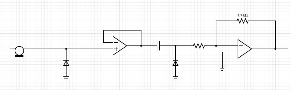
As OPA4191 has high input impedance, does it require DC bias diode?

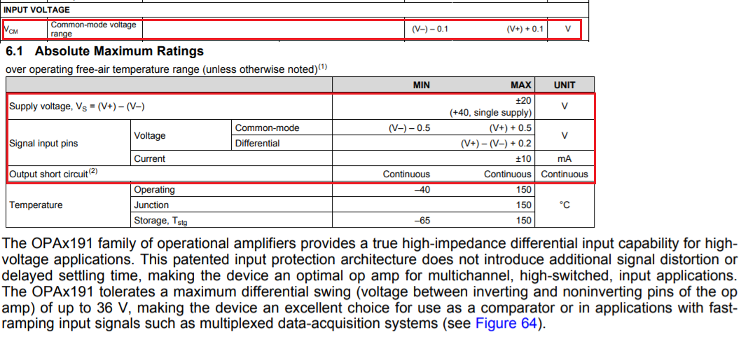
In the datasheet, 8.3.1 says something that I don't need  DC bias diode or it is something else?

Regards,

Jaehoon

  • These diodes are not called "bias diodes" but "protection diodes". During normal operation, they are never active.

    There are amplifiers that have built-in protection diodes between the two inputs. The OPA4191 does not have such diodes.

    If an amplifier has such diodes, they have side effects when the inputs are switched between different voltages. Section 8.3.1 tells you that the OPA4191 can be switched between different voltages without side effects. See the application note MUX-friendly precision operational amplifiers.

  • Hi Jaehoon,

    Thanks Clemens for the reply. He answered your questions. 

    If you need further assistant, please let us know.

    Best,

    Raymond

  • Hi Raymond,

    I might not be clear about using term "DC bias diode".

    Assuming that OP Amp has no input signal but only powered by +/- Vdd, if the input node is floating(no AC input) without proper DC bias, a small DC glitch or small DC input such as 1mV would be amplified by the open loop gain at the output node and result to be 100V easily. In order to prevent such case, a proper DC bias is needed in the input node and I think Diode connected to input and ground can provide a DC bias. 

    I guess 8.31. in the datasheet only explains the transient voltage protection. Am I missing something here?

    Regards,

    Jaehoon

  • Hi Jaehoon

    Assuming that OP Amp has no input signal but only powered by +/- Vdd, if the input node is floating(no AC input) without proper DC bias, a small DC glitch or small DC input such as 1mV would be amplified by the open loop gain at the output node and result to be 100V easily.

    If the Op Amp worked as comparator scenario is occurred, the output can only go up to +Vdd or go down to -Vdd. It can not go up to 100V in the circuit, because such potential does not exist in the connection. 

    If an unexpected transient conditions do occur at input or output pins, such transient events should be redirected away from the main body of op amp circuit,  as prescribed in Figure 60 and section 8.3.7 (Electrical Overstress) of the datasheet. 

    I guess 8.31. in the datasheet only explains the transient voltage protection. Am I missing something here?

    The input protection circuity described in section 8.3.1 is to prevent the input of the op amp to exceed the following absolute max. input voltage and current ratings. In addition, it described TI's input protection architecture features in the op amp, which it doe not distort the input signal or delay settling time. 

    If you have additional questions, please let us know. 

    Best,

    Raymond

  • Hi Raymond,

    Thanks for the reply.

    My question is proper DC bias is needed at the input of the OP Amps when the OP Amps is operating but the input signal is floating so that it could generate an arbitrary signal at the output. 

    I think high input impedance of OPA4191 can easily pick up the electromagnetic noise around it and generate the arbitrary noise signal at the output.

    Since my application is hearing aid circuit, such case results in noise sound to the user.

    Do you think I need to add diode to the input of the OP amp as describe in below circuit diagram? (the left most item is a microphone)

    Best regards,

    Jaehoon

  • A diode can prevent the voltage from going below 0 V, but it does not prevent floating.

    Consider using a pull-up or pull-down resistor, or a voltage divider to get a midpoint voltage.

  • Hi Jaehoon,

    My question is proper DC bias is needed at the input of the OP Amps when the OP Amps is operating but the input signal is floating so that it could generate an arbitrary signal at the output. 


    If the input signal is floating, you can insert a voltage divider to set the DC bias at the input of the op amp or use other biasing methods suggested by Clemens. 

    I think high input impedance of OPA4191 can easily pick up the electromagnetic noise around it and generate the arbitrary noise signal at the output. Since my application is hearing aid circuit, such case results in noise sound to the user.

    Since this is for hearing application, you may place a LPF with cutoff frequency at approx. 20kHz range, and this will attenuate high frequency noise at the input. The RC LPF is only attenuate the high frequency at a rate of -20dB/decade. If this is not adequate, you can put double LPFs (-40dB/decade) or use active filters like Sallen Key or MFB filters to attenuate high frequency at steeper roll off slope (e.g. 2nd, 3rd order LPF filters). 

    Do you think I need to add diode to the input of the OP amp as describe in below circuit diagram? (the left most item is a microphone)

    Since this is for hearing application, the system is likely operated in a battery. I do not see that there is a scenario that your input voltage is high enough that the input needs to be clamped. Please monitor the system's input signals, and see if such scenario can occur. I do not recommend to put extra components into a circuit, if it does not have a purpose. Please keep in mind that OPA4191 has certain built in protection features in the front end of the IC. If your application will exceed these protection features, then you may want to insert additional components to protect against the possible damages of op amps. 

    Best,

    Raymond