This thread has been locked.

If you have a related question, please click the "Ask a related question" button in the top right corner. The newly created question will be automatically linked to this question.

OPA340: Output waveform question for OPA340

Part Number: OPA340

Hi TI Expert,

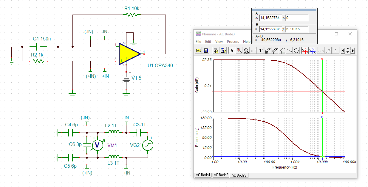
I design a TINA circuit for OPA340. When I run AC simulation from 10HZ to 1MHZ. I cannot understand for the Gain waveform.

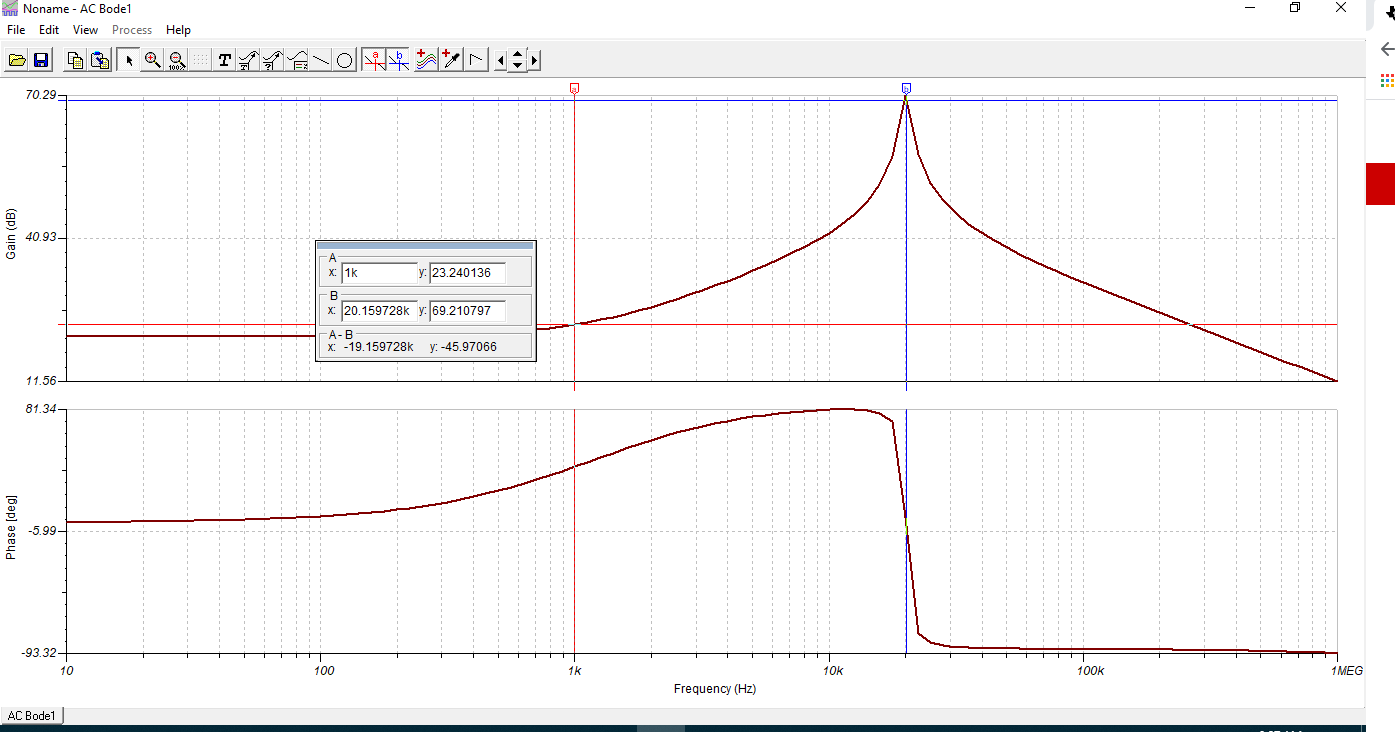
f=1/2πR2*C1=1KHZ, But the Gain waveform is raising from 1K to 20K. And the gain waveform is going down from 20K to 1M.

Why? Would you explain this and send me a  formula to  calculate Gain?

826.TSC

  • Hi Mickey,

    counterquestion: Why do you put a 150nF cap from the -input to signal ground? This erodes the phase margin and destabilizes the OPAmp:

    mickey_opa340.TSC

    Kai

  • Hi Mickey,

    Why? Would you explain this and send me a  formula to  calculate Gain?

    This is the issues:

    At DC, the circuit has a gain (10+1)=11 or 20.83 dB (assuming VG1=1)

    When Xc1 = R1, its frequency is 1061Hz or approx. 1kHz. --> this generate a zero in the circuit, the impedance of C1 and R2 is at 514.8 Ohm a 1kHz --> the circuit has a gain (1 + 10k/514.8)=20.4 --> The circuit's output is measured at 23.24dB or VG1 is approx. 0.712V at 1kHz based on the calculation. 

    As frequency increases,  the Xc1||R2 is further reducing, the circuit gain is increasing.The bode plot is shown that C1 is near short at approx. 20kHz, and it seems that there is an additional pole from parasitic of the circuit as frequency increases. 

    BTW, you will not want this sort of frequency behaviors in your circuit, which Kai is asking "why". 

    If you need further assistant, please let us know.

    Best,

    Raymond