This thread has been locked.

If you have a related question, please click the "Ask a related question" button in the top right corner. The newly created question will be automatically linked to this question.

OPA172: Made a preamp with OPA322 but have an issue

Part Number: OPA172
Other Parts Discussed in Thread: OPA322

I'm a newbie, so please bear with me.

I made this pleamp - https://www.ti.com/lit/ug/tidu765/tidu765.pdf - and it kind of works. But I made it with another mic model - https://mouser.com/datasheet/2/670/cmc-6027-24t-1777130.pdf. The difference is sensitivity - the original design mic has -42 dB and the one I used -26 dB. Everything else seems to be the same.

Now, since I just wanted to make it work as a prototype, the mic on my pcb is soldered with a pair of wires ~25 cm / 10" long. And when I connect 9V battery I start hearing only some kind of noise. But when I hold the mic capsule with my fingers I hear everything clearly. Once I leave it everything stops working again. The sound level is the same.

I honestly want to know the reason for this. So thank you in advance.

Alex

  • Someone told me to make mic wire very short so I did. And now there's no noise. But I have another issue - the sound level fades in ~3-5 min of operation. I use in-ear headphones for testing.

    Also, I just realized I used 2.2u 10V capacitors in my PCB. Could this be a reason for fading?

    Thank you.

  • Hi Alex,

    Using shorter wires is a good idea. This will reduce the chance of noise coupling on to the wires. When you create your PCB be sure to keep all your traces as short as possible. Here is a technical article for help laying out a PCB.

    The fading is likely not caused from using 10V capacitors in the signal chain. The voltage levels in the signal chain should be much lower than 10V.

    Note that C3 and C5 in the document is a 2.2uF capacitor but C2 is a 15pF capacitor. If C2 is 2.2uF the cut off frequency will be much lower than expected. However, it should not take 3-5 minutes for you to notice this. 

    Thank you,

    Tim Claycomb

  • Thank you for suggestions! I do have C2 = 10pF though (as in schematics).

    The traces are not long also.

    What I'm thinking is maybe mic sensitivity plays some role. In the doc - 2.1 Gain Calculation - the sensitivity is used for R2 value calculation. In my case the sensitivity is -26dB (not -35dB). This will give an R2 = 27 kOhm. But I think even with 75k it should work, maybe having some distortion... not sure.

    Also, the C2 is 15 pF in calculations but it's 10 pF in the schematics. Not much of a difference but C2 calculation uses R2 value. So C2 may be different for my mic.

  • Hi Alex,

    I would recommend you this circuit:

    Kai

  • Thank you Kai, I'll definitely try this one too.

    But first, I'd like to make the current one to work. Just to get some experience... well, I hope.

  • Hi Alex,

    Let us know how the testing goes!

    Thanks,

    Tim Claycomb

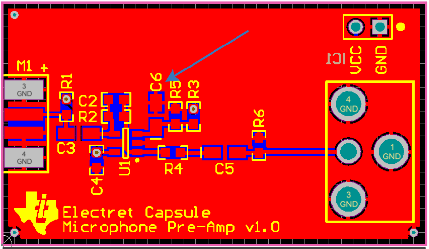
  • May I have another question on PCB layout? Is there a reason why C6 is the closest to opamp pin and not the R5, R3 here?

    Can I have R5 and R3 first and then C6? Is there any rules for this? I mean "Capacitor C6 is included to filter thermal noise created by the resistors and any noise which may be present on the power supply", so is this considered as a decoupling capacitor too? Then the rule "Place decoupling capacitors as close to the supply pins as possible." applies to it. Do I understand this right?

    Thank you!

  • Hi Alex,

    yes, C6 is a kind of decoupling capacitor and - following a rule of thumb - should be placed closest to the OPAmp.

    Kai

  • I'm sorry, but another question - there's a modification in the original document with OPA322 and VCC 5V. If I want to lower it down to 3.3V, I changed R1 to 2.4 Kohm which should correctly bias the mic.

    Also, there's an Opamp bias network (p.6). The values of R3 and R5 should not change. But "100kΩresistors were used in order to limit the power supply current drawn by this voltage divider. The current in the voltage divider will be: " - and the formula result for 9V is 45uA. But for the 3.3V it will be 16.5uA. The question is how is this current plays its role in the circuit. Are there any limits? I mean how is this current related to the opamp operation and its technical characteristics.

  • Hi Alex,

    The current drawn by these resistors should not necessarily effect the op amp performance. The current is kept to a minimum so that your supply voltage doesn't need to supply much current when you are running off a battery. For example, you wouldn't want to drain your battery by pulling 10mA through those resistors.

    Thank you,

    Tim Claycomb

  • Tim, thank you. Yes, I understand that part. I guess what I'm asking is is this current value somehow correlates to opamp technical specs? Any minimum/maximum current value that can be supplied to opamp?

    What if this current is 10pA? 100pA? etc

  • Hi Alex,

    just check it out with your circuit :-)

    Kai

  • ok, I think it relates to Input Bias Current of the opamp. In case of OPA322 it's ±8pA. Am I heading to the right direction?

  • Hi Alex,

    the only purpose of R3 and R5 is to provide an auxiliary "signal ground" at middsuply to allow the OPAmp to handle both half waves of the input signal coming from the microphone. As the exact value of this auxiliary voltage plays no role at all, the input bias current of OPAmp doesn't matter either. 10pA x 50kR = 0.5uV. That's the effect on the auxiliary voltage, a change of 0.5µV, if the input bias current is 10pA. But even if the input bias current was 1µA, the change would only be 1µA x 50kR = 50mV and would not play any role here either.

    The capacitor C6 serves not only as a low pass filter to suppress supply voltage ripple, but also decreases the impedance seen by the +input of OPAmp in the audio frequency range. This helps to minimize audio noise.

    Kai

  • Hi Kai,

    Thanks for the help on this!

    -Tim Claycomb

  • Thank you very much!