Other Parts Discussed in Thread: INA146, INA821, INA828, INA188
Hi,
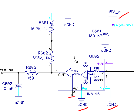
Can I make the gain of INA143 smaller than 10 by adding two resistors at the input side, seen below? I need the gain is around 7. If so, what is the bandwidth at G=7?
I also found INA146 is a OPA with gain adjustable, but the bandwidth is 50kHz at G=1. How about the bandwidth at G=7?
Thanks,
Hongmei