This thread has been locked.

If you have a related question, please click the "Ask a related question" button in the top right corner. The newly created question will be automatically linked to this question.

TLV1702: Problem with the comparator TLV1702

Part Number: TLV1702
Other Parts Discussed in Thread: LM393, LMC6772, LM339

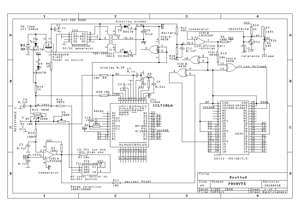
I have a resistor meter with LCD display and ICL7106 AD.

The ICL7106 is quite low resolution 3.5 digits.

I need more from 0.0 ohm to 1999 ohms.

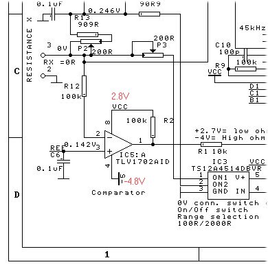
I have made a external range switch with TSA4514DBVR.

It needs a comparator to know when the range switch ( 0.142V this case) works and a decimal point).

TSAA45  should go to open, when I connect resistor input together. 

It doesn't work. The output of the TLV1702 ( pin 1)  is always down ( -4.8V).

If I switch the rage manually everything works right.

I was wondering if the positive power supply was too low.

So I connected external 1,5V battery to pin 8  Now power was 4.5V, but no help.

Then I I exchanged  a  new  TLV1702 device, no help.

Then I ordered a old LM393 device.

It doesn't work better either.

I wonder what I have made wrong?.

The input pin 2 is 0V and pin 3 is 0.142V, but output is -4.8V.

If I connect pin 2 to pin together, the output goes to 2.8V. 

Can the output resistor be too high?

Regards

Pekka Ritamaki

Finland

  • Hello Pekka,

    From what you describe, it should work. The TLV1702 should work fine on 7.6V. It is a R-R input, so as long as the input voltages are between -4.8 and 2.8 it should function.

    Shorting the inputs does cause the output to toggle, so the pull-up is working and the output is not being "held-up" externally. 100K is on the high-side for a pull-up, but not unreasonable if you wish to save power and speed is not an issue. What is on the other side of R1? What is it driving? What are the actual output "low" and "high" voltages? Can the devices down-stream of the output handle -4.2V?

    How is the 0.142V generated? Have you measured it and confirmed it is correct?

    Do note that the typical 10M input impedance of most DMM's can load a resistor divider causing the voltage to read lower than calculated - so be aware of that.

    Same for the positive input. Is it really zero?

    The 1702 and 339 are bipolar input devices, so they have bias current flowing OUT of the input (flowing out from V+ towards ground through the inputs). So on the positive input, you could see 500uV (TLV1702) or 2.5mV (LM393) generated across the 100k (R12). But this is not enough to cause the failure, unless the inputs were somehow damaged.

    I would recommend a LMC6772, which has a CMOS input with femtoamps of bias current - which would eliminate any issues with bias current (and truly a "high impedance" input). It also eliminates the bias current injection that may also interfere wit the reading.

    Can you provide the entire schematic - at least the parts containing the input signals and where the comparator output goes? There is something being overlooked.


  •  
    Paul Grohe
    Thank you for your comments
    This is the first time, when I got real electronics comments about my circuit.
    I include the full schematic.
    The device should start automatically when the resistor is connected on.
    It is done by P-FET PMV50.
    It gets a starting current from D2 and operating current from D4.
    Then there is a DC/DC converter, which makes +2.8V and -5.2V.
    These are for ICL7106 and it makes these voltages.
    It is done by MAX845 and Halo transformer.
    Then there is a low voltage battery detector.
    It works 2.75V.
    It generates LOW to LCD the device.
    It may be too high, but I can change it.
    Then there is  a reference generator ZR431.
    It generates 2,5V, but I take from it 0.142V ( with R7 and R4) which is needed for the input range (under 100 ohm and over 100 ohms). 
    A CD4030 is  the four exclusive OR functions to control LCD point and LOW voltage indicator.
    They need exclusive Or  functions to control normal LCD (not with back panel LCD)
    The input current is measured by R13 (909 ohms) and P2 (200 ohms).
    They are done for the calibration work.
    The low range is done R16 (90.9 ohms and P3 ( 200 ohms).
    They will work at the lower range.
    The measured resistance X  is measured by input voltage.
    The ADC and display shows 1000* Vrx/ current voltage.
    The IC5:A is the comparator (LM393, which doesn't work) and the range  switch  is a   IC3 TS120A451.
    ==
    I try to connect IC5:A  pin 4 from -5V to 0V.
    ==
    I have done a working device to the same customer with PIC18F47J53.
    It has a 12 bit AD converter and many more good things.
    It needed  35 exclusive functions to control LCD.
    It was done by a program.
    It worked well, but then the customer found old ICL7106 devices and wanted me to do the same with these old devise.
    Regards
    Pekka Ritamaki

  • Hi Pekka,

    the full schematic didn't come through. Please post again by using the "Insert File" button (paperclip) in the header of input box.

    Kai

  • Kai the symbol was quite different and  I think it was a microphone, that is why I paste the file, but it doesn't succeed.

    Pekka Ritamaki

    .

  • Now we can see it, Pekka :-)

    Kai

  • Hello Pekka,

    I see a few issue.

    The low batt detector, IC5B has the input range violated on both inputs. The specified input range is Vcc-1.5V (Vcc-2V at cold). Your V+ supply is 2.8V, which would make the valid input range up to +1.3V at room temp, and +0.8V at cold. You are applying 2.4 and 2.75V input signals. You are squareley in the dead zone and I would expect failures. You are probably not noticing because the output generally goes low when both of the upper input ranges are violated - and low means good batt. See section 8.2.2.1 in the LM393 datasheet. This should not affect the other channel, tho.

    Again, I would recommend a rail-to-rail input device, such as the LMC6772 or TLV1702 to eliminate the voltage range issue.

    You are relying on the clamps on the inputs of the logic gates to handle the -4.8V "low" voltage. That is ~450uA on the negative supply per input when low.

    Have you monitored all the supply voltages? Can the negative supply support that extra current?

    You may want to review the LM339 family application note, particularly section 2.3:

     https://www.ti.com/lit/an/snoaa35a/snoaa35a.pdf

  • Paul Grohe

    Thank you again your good review.

    I already mention the power operation was not right at IC5:B.

    I modify this according the drawing kuntg.jpg. 

    I doesn't  change the resistance change operation .

    ===

    You  mentioned the power supply filtering.

    This was quite good operation.

    I added two 4.7uF capacitors to the power supply.

    This was a great movement to better working.

    Zero ohms worked now well! 

    I added two 4.7uF capacitor to +/- power supply.

    It has a great effect,

    I changed R12  100k to 10 k. This has no effect.

    I changed the output of the comparator  (R2) from 100k to 2k2 resistor  

    It had now effect.

    ===

    Then I checked 100 ohms measuring device.

    I doesn't worked well. 

    It showed 140 ohms at high  ranges ( decimal point was removed)

    Then I checked a little lower value 71.8 ohms. 

    It showed 319 ohms at higher range, which was not right.

    The output of LM393 was not high or low, but about 0V.

    ==

    Then I checked 1k resistor.

    It worked well, the display was 1002.

    The LM393 doesn't worked well,

    I should give +Vcc or -VCC, not between.

    You  intestine LMC6772.

    This device is in my own supply (TME), but they have not made an order, so they have 0 pcs. 

    ==

    Doesn't LM393 work as a comapator? 

    I have tied feedback resistor from the comparator output to -input. 

    It was 6M8, a 1M and 220k.

    I didn't helped. but it was before I added the power supply capacitors.

    Maybe I have to try once again.

    I read the https://www.ti.com/lit/an/snoaa35a/snoaa35a.pdf document.

    Regards

    Pekka Ritamaki

  • Pekka

    it may be best to simplify what your circuit is and exactly what result you are seeing that is not correct.  It is ok if you draw it freehand and upload.  I also do not see any screen shots from an oscilloscope showing the problem.  would it be possible to show us the improper result that you are observing in that fashion.

    Lastly, you mentioned applying negative feedback to the comparator.  what is your intent with that?  

    Sorry I cannot provide more insight into the problem but hopefully we can help resolve once it is more clear.

    Thanks for your patience as we try to resolve this issue.

    Chuck

  • Chuck

    The comparator feedback was a solution!

    I put a 1M resistor from comparator output to positively input.

    I increase the capacitor value to 4.7uF, but I am not sure if it need.

    The range works now at 80 ohms to higher range.

    It works also from higher range to lower range a little more resistor, about 90 ohms.

    The higher range is little bit slow. but I can fix it.

    ==

    Why I do not use oscilloscope?

    I have TEK TDS420 scope, but it is broken.

    I  can't use a clear  switch to open the scope.

    It is used to broke ( 30 years!), 

    I succeed to get the other switch set , which was right clear button, it doesn't work either.

    I added a separate . clear switch, but this doesn't help.

    ==

    I put my last schematic on. 

    Well, now it woks.

    I do some testing,

    Thank you for your suggestions.

    I can't see oscillograms for the power supply.

    Regards

    Pekka Ritamaki

  • Glad to hear that it’s working now. Best of luck with your system.

    Chuck

  • Chuck

    I need still to make circuit board, manufacture it, purchase the components, place the components, test it, apply to the customer.

    Let see if everything works.

    ==

    I changed  the feedback resistor from 1M to 470k .

    ==

    Many thanks

    I think I can't live without s scope.

    Regards

    Pekka Ritamöki