This thread has been locked.

If you have a related question, please click the "Ask a related question" button in the top right corner. The newly created question will be automatically linked to this question.

INA818: INA818 in the negative feedback loop of opamp circuit: Not working

Part Number: INA818
Other Parts Discussed in Thread: LMH6321, OPA2192, BUF634

Dear TI Technical Support Team,

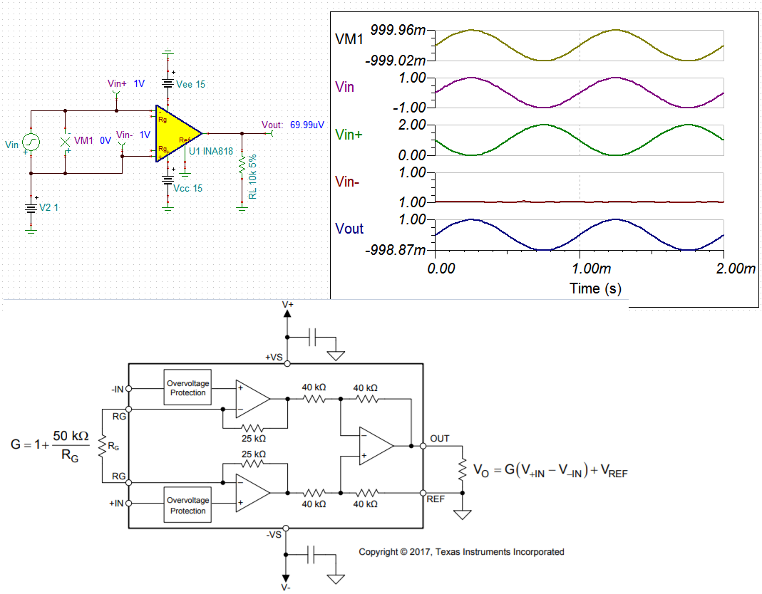
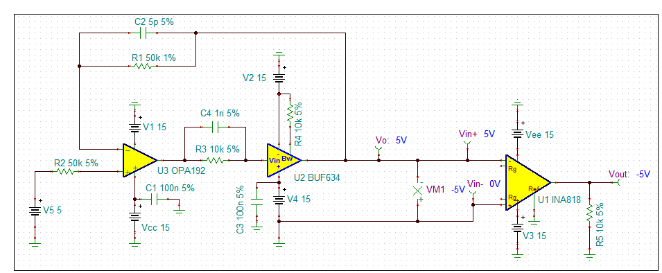
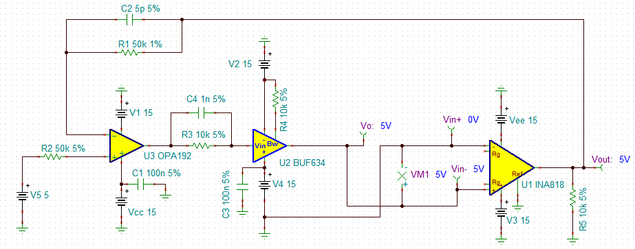
I have designed opamp circuit which has INA818 in the feedback loop. Both opamp and INA 818 are supplied with +15V and -15V. INA818 is used in gain=1 mode (Rg is open circuit).

I want to achieve following. For example, when INA 818 Input+=1V and set point from DAC is 2V then opamp must adjust itsef and output (thus Input- of INA818) must go to the -1V so that opamp inputs are at same voltage (2V). Setpoint from DAC can be between +12V and -12V. To test the setup and I connected Input + to ground.

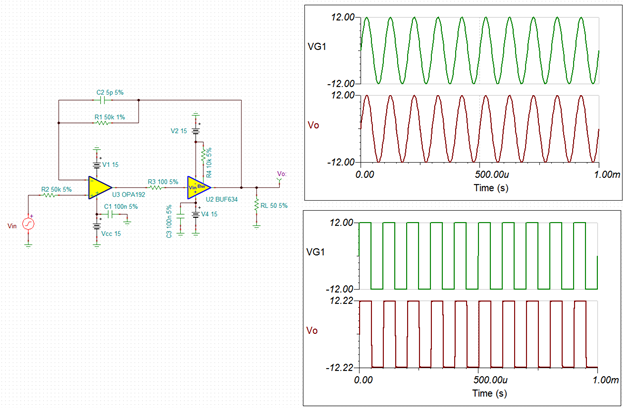
I just connected 10k to the output of the opamp and I applied voltage  to the positive input of the OPA2192. I expected that Negative input of OPA2192 thus output of INA818 to be at same voltage as opamp positive input (usual opamp characteristic). But INA818 output saturates and goes to near -15 or 15V (sth like 13.5V). When I remove INA818 and used opamp in buffer mode, as expected it worked. I changed INA818 with new one to see if the problem was related to it, again nothing changed. Whatever voltage I applied (set point from DAC), INA818 input was at -13.5 or +13.5V (Input + was at ground). I was also using LMH6321 to get high current output from opamp, but when I see this problem I removed it and tested the overall circuit as shown in figure. 

Could you please help me to solve this problem?

Thank you for the help, 

Ahmet

  • Hi Ahmet,

    Q: I want to achieve following. For example, when INA 818 Input+=1V and set point from DAC is 2V then opamp must adjust itsef and output (thus Input- of INA818) must go to the -1V so that opamp inputs are at same voltage (2V). Setpoint from DAC can be between +12V and -12V. To test the setup and I connected Input + to ground.


    INA818 is an instrumentation amplifier, and it provides gains on the difference of G(Vin+ - Vin-) + Vref. Since Vref =0 and Gain =1, Vout = Vin+ - Vin- is the transfer function. Most importantly, it amplifiers the changes of Vin+ - Vin- in differences of (DC + AC) signals. 

    I am not quite sure what you are trying to do with the feedback circuit. Can you feed us with more details about your design requirements? LMH6321 is 300mA  high speed buffer driver, and it works differently from INA818  instrumentation amplifier. 

    Enclosed is the INA818 simulation. 

    /cfs-file/__key/communityserver-discussions-components-files/14/INA818-E2E-09112020.TSC

    Best,

    Raymond

  • Two inverting amplifiers in a loop are positive feedback.

    For starters you need to reverse either:

    1. The op amp inputs, or

    2. The instrumentation amp inputs

  • Hi Raymond, 

    Thank you for the information and details you provided.

    In my design, I am using LMH6321 to boost opamp output as it seemed me an easy way rather than using some npn pnp and giving attention Vbe drop and etc. LMH6321 was perfect for me at that point. In my circuit I am appling voltage from DAC to positive input of opa2192. By using opamp nature I want the negative input thus output of INA818 to be same as setpoint from DAC. 

    The dut has 4 leads. When current passes through 1 and 3, voltage appears between 2 and 4. I want to control this voltage, when I apply setpoint from DAC part, opamp will adjust itself and source or sink current such that voltage difference between 2 and 4 of DUT are same as setpoint.

    Instead of DUT, to test the setup, I used resistor. I shorted 2&3 and 1&4 (in previous picture, Input + was at gnd and 1&4 was output of opamp). As input+ is at ground, I expected negative input of INA to be at (-1)*setpoint      so that output of INA=setpoint (0 - (-setpoint)). But it did not worked, the output was saturating. 

    In theory, I expected this to work, but it did not. 

    Regards,

    Ahmet

  • Hi Ahmet,

    I put together a circuit and see if it meets your requirements. I am using BUF634 instead of LMH6321. Either buffers should work. The phase margin of the circuit is approx. 68 degree with BW is approx. 3.0 MHz.

    If you want to have LMH6321, I will get the simulation for you as well. Or you want to use INA818 instr. op amp. Please let me know. 

    /cfs-file/__key/communityserver-discussions-components-files/14/OPA192-_2B00_-BUF634-09112020.TSC

    Best,

    Raymond

  • Hi Raymod,

    Thank you for the files you provided. I also made simulations with them.

    When I use BUF634 + OPA2192 (normal buffer), as expected, opa2192 positive and negative inputs are equal.

    When I include INA818 into the loop, as you see from the analysis that, opap out goes to supply and saturates. It was my actual problem. My circuit is similiar to this simulation, and I am having same issues. I am trying to understand the cause of it. 

    I expected output of opa2192 thus out of BUF634 to be at -5V so that INA818 out is +5V and opamp inputs are at same voltage.

    Could you please comment why this is not happening. What is my mistake? 

    Thank you in advance.

    Regards,

    Ahmet 

  • Hello Gerard,

    Thank you for this comment,

    It worked in the simulation. As you said, in reality, ı was making positive feedback.

    Thank you for your help,

    Ahmet

  • Hi Ahmet,

    Before you fed back the output from INA818, the DC bias looks like the following. In this circuit Vo=5V and Vout= -5V. Now, if you feed back -5V back to INA192's inverting input, then you feedback positive (negative*negative) Vout to the V- of U3. 

    If you feed the voltage back in the following manner, then Vout will be 5V, but I am not sure what you are trying to do. 

    Best,

    Raymond