Hi,
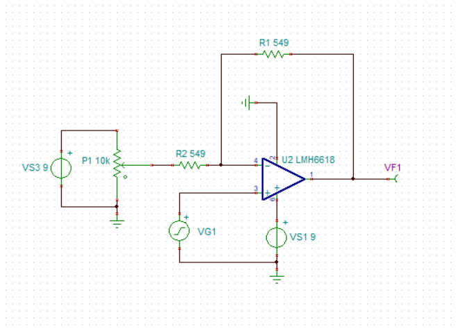
I have implemented a differential amplifier circuitry using LMH6618 op-amp (as shown in the attached file). At the inverting input I have applied a DC voltage through a pot and at the non-inverting pin I have applied a sine wave with DC shift of 2.5V. My intention is to remove the DC voltage of sine wave input at the output. From theoretical analysis I guess the output should be Vout = Vdc*(-Rf/R1) + Vin*(1 + Rf/R1). According to this formula, I applied 5V DC at the inverting input. But the waveform suggests that the sine wave at the output is still DC shifted. Moreover I was expecting the sine wave to be twice the amplitude at the non-inverting input. But the waveform gain is less than this. Can anyone help me analyse the circuit and what should I do to remove DC shift of sine wave? This circuit is part of my project where I'm trying to remove DC shift of a video signal.
Thanks,
Sandeep M.