This thread has been locked.

If you have a related question, please click the "Ask a related question" button in the top right corner. The newly created question will be automatically linked to this question.

INA260: Back feed?

Part Number: INA260

Hello,

I hand soldered an INA260 to a DIP breakout board and I am a little concerned about my job of doing so.  Also, I don't really know what I'm doing.

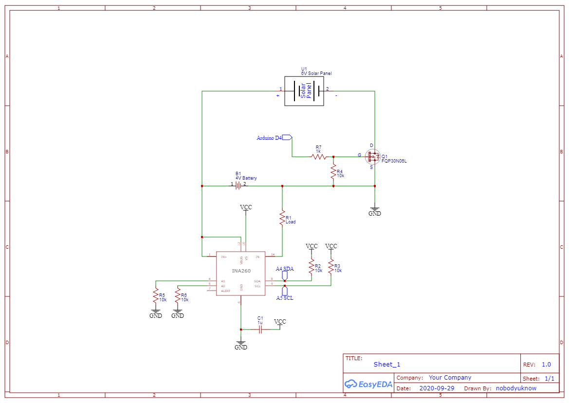
I have the INA260 attached to an Arduino Mini and am trying to use it to measure a solar panel.  I got "sensible" readings until I tried to attach a mosfet to connect and disconnect the panel ( I just used a 4V battery for this testing). Then I noticed that the battery was never completely disconnecting.  The gate is getting a back fed voltage of about 2V from somewhere and I worry that it may be from my soldering of the INA260 --- too much heat or maybe a solder short beneath the chip.

I'm trying to find the source of this back fed voltage.

With the INA260 completely disconnected from everything but the positive terminal of the 4V battery to the three + inputs, I read about 4.3V between pins 1-3 (+) and  pins 14-16 (-)     and the battery negative terminal.

Pin 13(NC) is 0V.

All of the other pins read about 2.6V-2.8V.

My question :

Is this to be expected/normal or is there a short somewhere? Perhaps in my soldering? 

I don't know enough not to ignore my gut feeling that pins 4-12 should somehow be isolated from pins 1-3 and 14-16 and have no voltage on them.

Thank you for any insight, Robby R

  • Hey Robby,

    Welcome and thank you for posting to the forum. I am looking this over now and will give a response before end of business hours.

    Sincerely,

    Peter

  • Hey Robby,

    Would you please send a schematic of how the MOSFET is being driven and for INA260?

    It is not uncommon for the voltage at other pins in the device to rise to some value when they are left all floating. There could be some current flowing from IN+ pins to and into the device. There also could be a short in the soldering. You could send a photo just to be sure.

    Why are you disconnecting the INA260 because there is 2V at the gate? Maybe the gate of FET needs some pull-down resistance? I would first make sure that you can operate the FET as desired before debugging the INA260.

    While the digital logic and input pins are separate functional blocks in the device, they may share some common-ground or internal power rails, so there is no true complete isolation between these systems and thus it is very possible that circulating DC return currents will raise the voltages at other pins in the device. In the end these pins should not be floating anyway and they should be pulled up or down.

    Hope this helps.

    Peter Iliya

  • Hi Peter,

    Thanks for looking at this.  It took me a while to figure out the schematic drawing bit, but the attached schematic is what I have (I think).  I also tried the mosfet on the plus side of the solar panel.  I've only successfully used a mosfet for turning an LED on and off before --- sooo??? Thanks

  • Hey Robby,

    Thanks for sending this. I would first recommend changing R5 and R6 from 10k to 0Ω resistors. The address pins are supposed to be pulled up or down with just a trace, no resistance should be at the address pins. I don't know if this is the problem, but it is not a bad place to start with debug.

    After fixing R5 and R6 and retesting, could you see if you can turn the FET on and off with the Arduino and the INA260 completely depopulated from the PCB? You would then need to add a short in between the missing shunt resistance from R! to B1. If you cannot switch off the FET properly with the INA260 removed from the board, then this is an issue with FETs configuration or Arduino's D4 pin.

    Sincerely,

    Peter

  • Hi,

    I'm assuming a 0 Ohm resistor is just a wire.  And R! is R1  Right?

    I don't understand "add a short in between the missing shunt resistance from R! to B1" that you mentioned. 

    Peter Iliya said:

    You would then need to add a short in between the missing shunt resistance from R! to B1. If you cannot switch off the FET properly with the INA260 removed from the board, then this is an issue with FETs configuration or Arduino's D4 pin.

    Thank you very much.  I'll try this tonight, Robby

  • Oh, I think I understand about the "missing shunt".  You mean in place of the INA260 shunt between pins (1,2,3) and (14,15,16), right?

    Thanks, Robby

  • Hey Robby,

    Yes that is exactly what I am saying. A wire should be placed from B1 to R1 to replace missing shunt resistance of INA260.

    Sincerely,

    Peter

  • Hi Peter,

    I've been playing around with this some tonight, and I think I need to learn a little more about mosfets --- namely coming up with the voltage to completely turn it on (I think).  Seems like the arduino pin is working fine in the test setup you recommended, but I'm losing D/S voltage across the mosfet which from what I think I know means it has too much resistance due to too low of a gate voltage --- so it might be a few days before I get back to you while I study up on this.

    Thanks for your help, Robby

  • Hey Robby,

    Maybe a FET with a lower Rds(on) would be better? If you could probe the gate and drain voltages that would be great too.

    Sincerely,

    Peter