Other Parts Discussed in Thread: OPA857, OPA858, OPA855, OPA859
Number: CS0300295 Contact: Andrea Papi First name: Andrea Last name: Papi Short description: TIA Design for PMT Tube Phone: 003907558527543907 Email: andrea.papi@pg.infn.it Company: INFN Company phone: Language: English State: Open Provide case details or comments: Hi,
we at Italian National Institute of Nuclear Physiscs in Perugia Italy, are trying to develop a Low Light Leak System for a RICH detector on a CERN HEP Experiment.
We have to use PMT from Hamamatsu R7400U for low leak light detection in a Dark Box where are the Photon Counting PMT for the RICH detector. If there is a low light leak in the box we have to turn off the HV Bias of the detectors to protect the Photon Counting System.
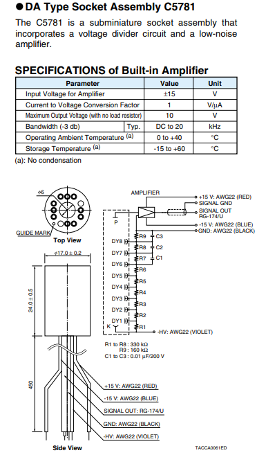
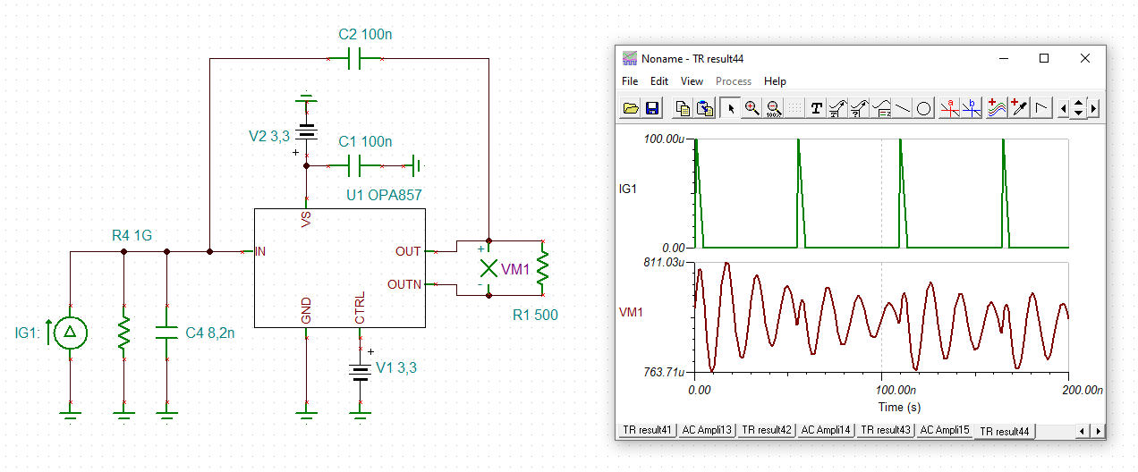
The signal from the PMT come form 100 meters of RG58 cable (Tot Cin is 8.2nF Cable) with BNC connectors, we need to read the Photocurrent and convert this current in a linear voltage.
Now the low light rate is 1.3Mhz and the High light rate (photons) is 18Mhz, prom PMT pulse, we have to place the alarm threshold near 15Mhz. The counting rate is quite high and the PMT pulses will overlap each other and produce a continuous current (Photocurrent) and may be an hybrid solution between an Charge Sensitive Premapli and TIA could be the best circuit.
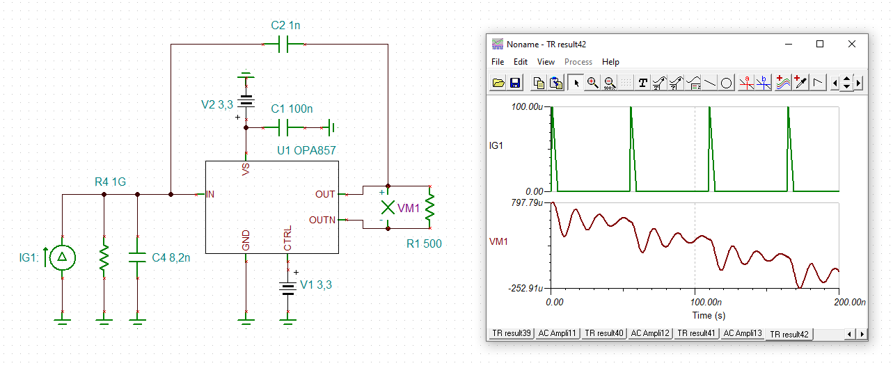
The costant time of the CF and RF should be more than 10 times the T of the maximun pulse PMT frequency 18Mhz (I mean 500ns).
We need at maximun 20 sensors and conditioning circuts for the 20 dark box of the experiment then the solution with custom design.
We want to use a TIA System to convert current in voltage coupled in DC then we send the output buffered to a comparator and set two alarm signals one is TTL and the other is LVDS signals to turn off the HV Bias of the PMT.
We'd like to know if your OPA857 Evaluation Board can fits our need for prorotype, we will have 15 PMT R7400U to monitor 15 dark box each containing 64 multianode PMT to protect.
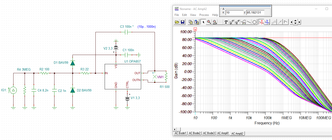
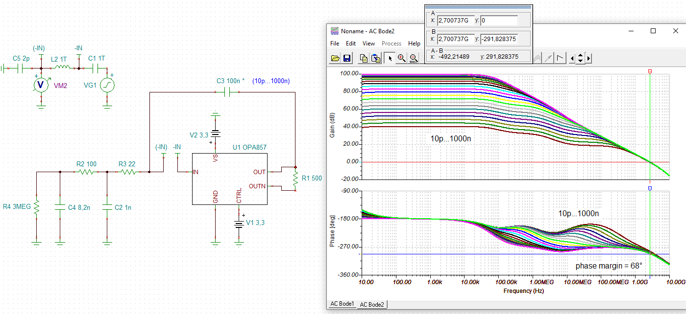
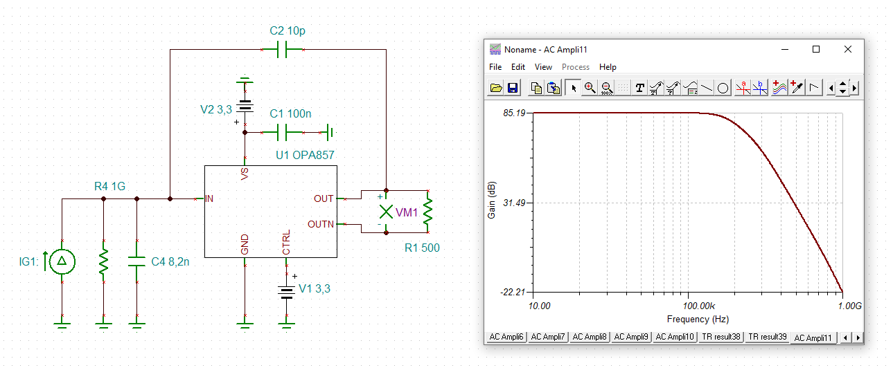
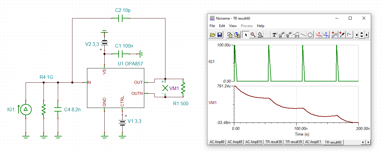
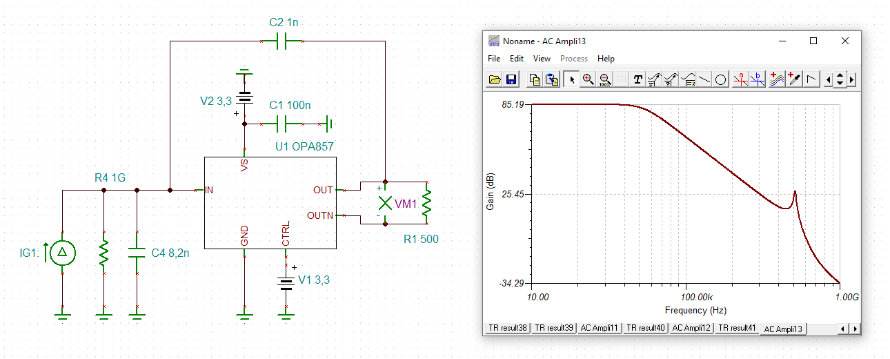
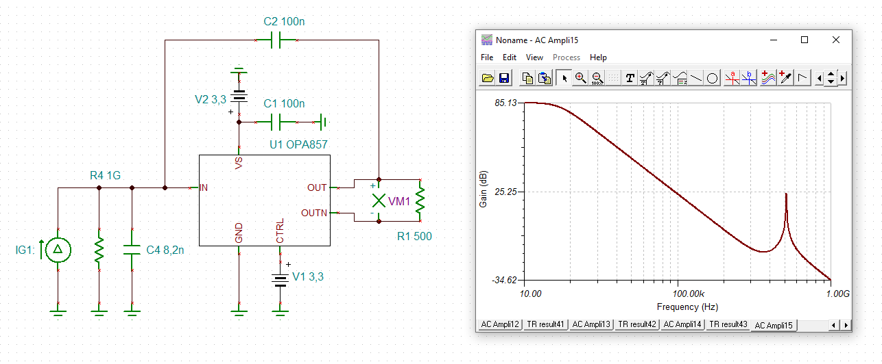
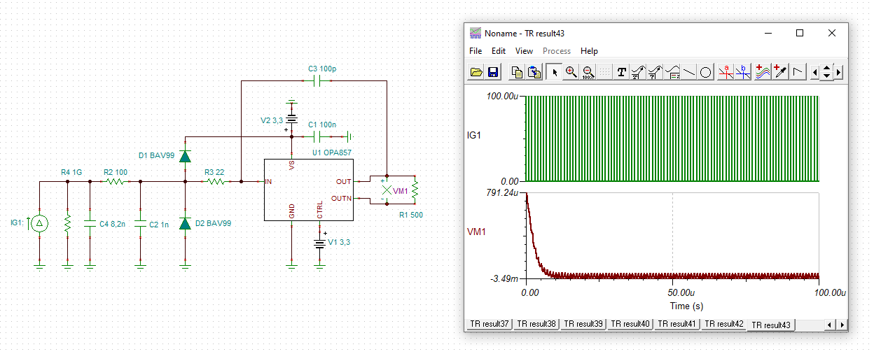
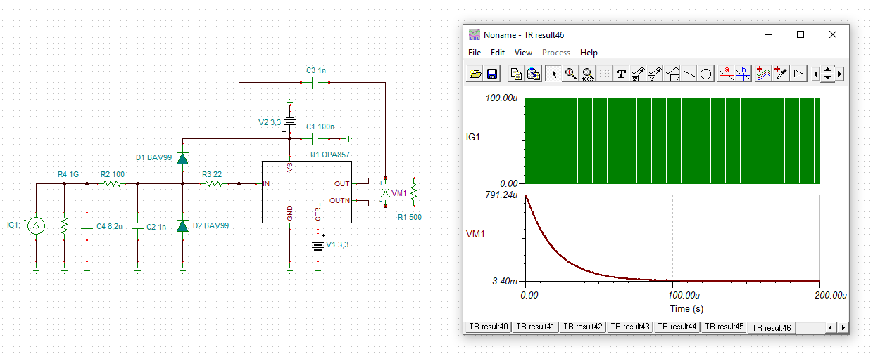
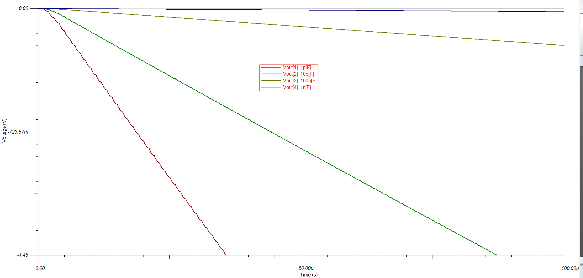
We will need to know the tau of the TIA (Opa857) expecially if the long 100 meters of RG58 cable at the input can create problem to your chip, but I know that it is possible to use RF and CF externally expecially CF to compesate the Cin (from cable), we are not interested to the bandwidth because we are not woeking in pulse mode but we want to convert a current-to a voltage level on the TIA output we will plase a Low Pass Filter and a buffer to drive the comparator.
These the data of the design:
C cable RG58 (100 meters) = 8.2nF
Ci = OPA = Cdiff + Ccm = ....
RF = 1K /2.2K
CF = Sqare Root of = Cc+ Ci / 2 pai Rf x GBP (OPA 857) ( compesating C cable).
We wait your hints and tips and error detection for our assumptions.
Thank you.
Kind regards.
Andrea Papi.
Perugia Italy INFN.
075 5852754
www.pg.infn.it