This thread has been locked.

If you have a related question, please click the "Ask a related question" button in the top right corner. The newly created question will be automatically linked to this question.

LMP2012QML-SP: LMP2012QML worst case gain margin

Part Number: LMP2012QML-SP
Other Parts Discussed in Thread: LMP2012QML, LMP2012

Hi.

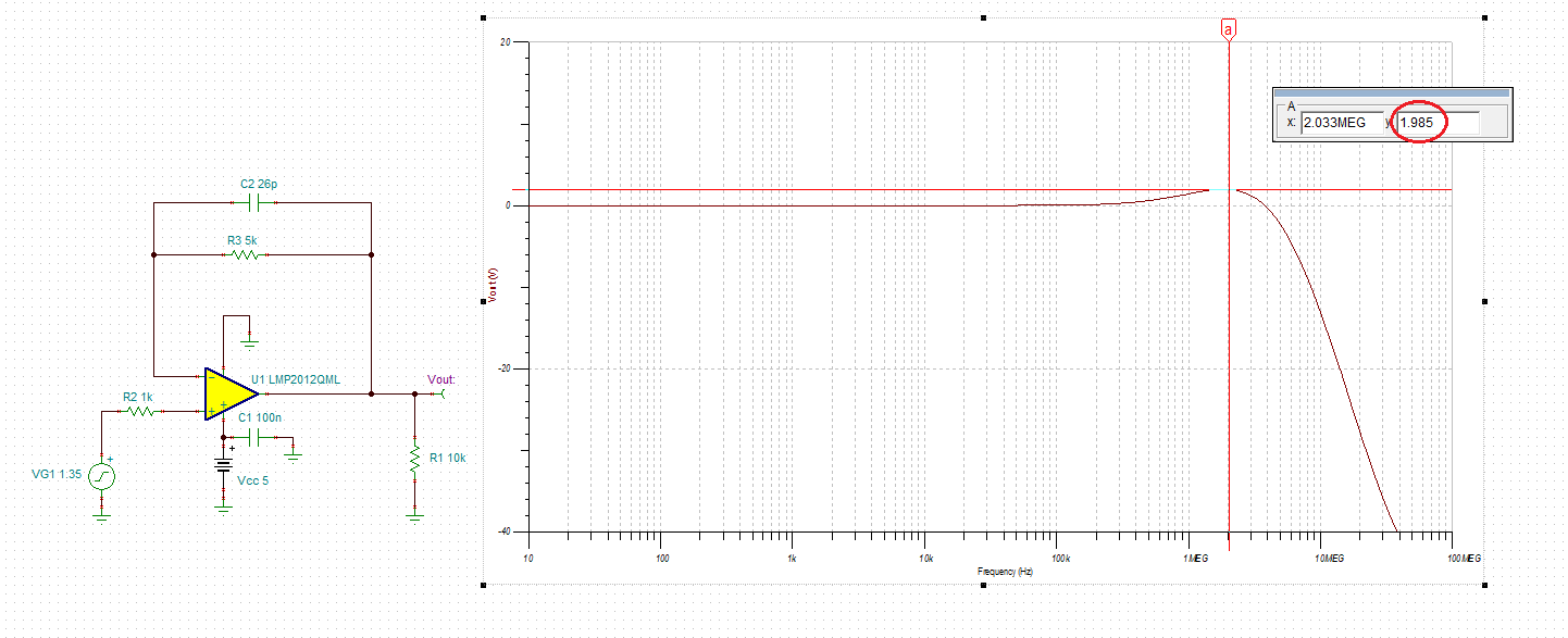
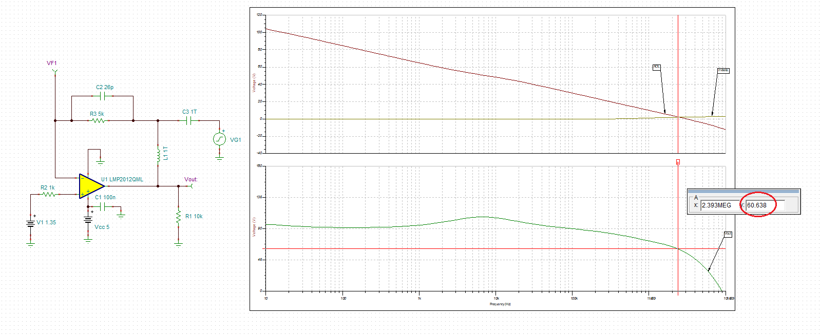
I am using LMP2012QML in 2 opamp instrumentation amplifier configuration with the one opamp being near unit gain and pspice simulation has GM (gain margin) of 14db, same as specified in datasheet.

For worst case analysis a consultant has toleranced the LMP2012 model to have bandwidth of 1 to 5Mhz (from datasheet).  Using the modified model the worst case GM is 7.5dB which is below our 10dB goal.

Is this a valid gain margin tolerance for  LMP2012 or a modeling error?  Does TI have any data on worst case, EOL gain and phase margin for the LMP2012QML. Currently datasheet just has typical.

Thanks,

Mike

  • Hi Michael,

    Phase margin is highly dependent on the circuit configuration, the typical phase margins shown in the datasheet are for unity gain. However, it's true that when an amplifier starts to run out of gain, the phase margin suffers, so theoretically a device with a GBW near the "min" and a device with GBW near the "max" will have different phase responses.

    Can you share more information on your circuit configuration, such as a schematic or PSPICE design? Are both of the two amplifiers in your instrumentation amplifier LMP2012s, or only the device in near unity gain? What supplies are you powering the LMP2012 with?

    Thanks,

    Jon

  • JMac, you answered about phase margin, he was asking about gain margin, 

    It is very rare, however, for a good phase margin design to have an oscillation related to poor gain margin. Normally we focus on phase margin - 

    Well Michael, where did you get that min gain margin spec and do you have a min phase margin target - and yes, impossible to really answer without a schematic. 

    That 1 to 5MHz range seems huge, there was a recent discussion where we kind of zeroed in on +/-30% GBP tolerance for untrimmed parts (supply current) and +/-20% for trimmed. 

  • When the LMP2012 PSPICE internal model is toleranced to make the gain bandwidth 5Mhz from the typical 3Mhz the gain increases about 7dB (based on slope of the gain in the bode plot).

    So a 14db unity gain margin becomes 7dB.  The typical goal for our Hi Rel Aerospace customers is a 30deg,10dB phase and gain margin.  We can likely sell off the 7dB but not ideal.

    If we had data that GBP tolerance were indeed +/-30% rather than the +66% that would help but hopefully customer will accept analysis margins as is. Thanks.

  • Micheal,

    Below please see three rules of thumb that assure stability of the system over process, temperature and supply variations:

    1. Minimum phase margin of 45 degrees, which to first-order may be tied to the max 25% small-signal overshoot - see below:

     2. Minimum phase margin of 45 degrees, which to first-order may be tied to the max 2.5dB AC gain peaking - see below:

    3. The minimum gain margin of 6dB - see below.

    The circuit below is very stable with 60 degrees

    phase margin - see below.

    If you need further assistance, please provide the schematic by modifing attached circuit - a picture is worth thousand words.

    Also, please review TI Precision Lab videos disscusing stability issues:

    LMP2012 AC stability.TSC

  • Hi Michael,

    My apologies, I misunderstood your question.

    The 1/5MHz min/max GBW values appear to have originated with the MIL-STD-883, Method 5005 testing. They are the specified max and min values for that testing, as shown on Page 7 of the SMD document. So while the typical pre-radiation values will likely be closer to the +/-30% tolerance that Michael Steffes mentioned (perhaps around 2-4MHz), unfortunately only the 1/5MHz limits are guaranteed post-rad.

    Thanks,

    Jon