This thread has been locked.

If you have a related question, please click the "Ask a related question" button in the top right corner. The newly created question will be automatically linked to this question.

PSpice simulation: Non-linear behavior detected in a simplest schematic

Other Parts Discussed in Thread: TINA-TI

Hello,

Simulating this simplest case (please, see schematic in attached pdf), I've got this starnge waveform:

How this non-linear shape resulted out from linear schematic ?

Thanks,

Sincerely,

Pavel.

P.S. Additional question: how specify internal resistance of voltage source ?

boucle_resonance_sch.pdf

  • Hi Pavel,

    what type of inductance is "Lbreak"?

    Kai

  • Hi Kai,

    What do you mean under "type" ?

    I picked this unductance from Breakout library.

  • Hi Pavel,

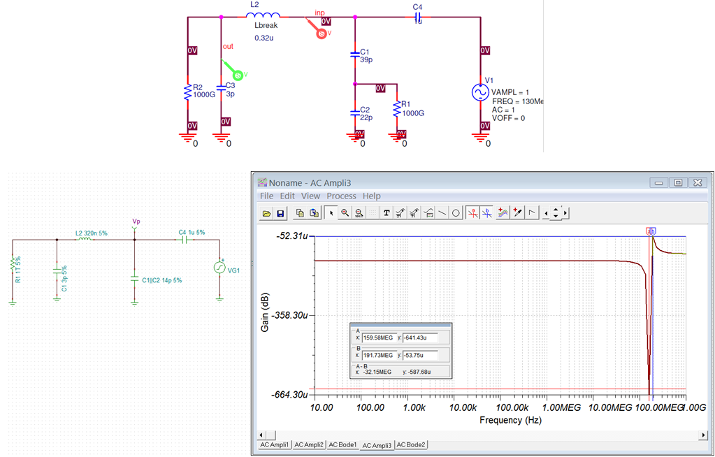
    You do not have a linear circuit. You have L2 and C3, and they are 2nd order filter and it has high Q in the schematic. I made an equivalent circuit, and see the AC response. The only AC short you have is C4 or 1u. C1, C2 and C3 are not AC short in the circuit, because of their values (C1 is in series with C2 or 14pf).

    If you have any additional questions, please let us know.

    Best,

    Raymond

  • Hi Raymond,

    Thank you for feedback.

    Frankly speaking I didn't understand your statement "You do not have a linear circuit". There is no nonlinear element, such as a transistor. How can a circuit be nonlinear if it does not contain any nonlinear elements?

    Sincerely,

    Pavel.

  • Hi Pavel,

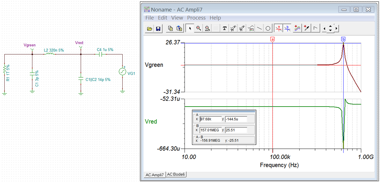
    My misuse of terms. When I see yout plot and I thought that there is an oscillation that may be caused by Q. Yes, there is Q in your circuit as shown in the captured image below. However, it is occurred at 157MHz. 

    Then I look at your plot carefully, I noticed the x-axis scale. You have 90msec to 100msec in time axis and there are approx. 13 red input signals or the input frequency is approx. 10ms/13 or 1300 Hz. Your schematic's injection signal indicated 130MHz, so the plot and schematic does not match. Can you check on your schematic vs. plot. 

    Best,

    Raymond

  • Hi Raymond,

    I've just checked my simulation.

    Here is schematic (indeed resonance isn't at 130MHz):

    Here is transcient:

    And here is AC:

    The non-linear behavior decreases when I increase the resistance R5. At 50 Ohm, eg it disappears. So I think it has to do with non-matching.

    Sincerely,

    Pavel.

  • Hi Kai,

    What tool did you use ?

    Does it allow to specify internal resistance of VG1 ?

    Sincerely,

    Pavel.

  • Hi Pavel,

    Kai and I are using Tina simulation tool as shown in the link below. 

    https://www.ti.com/tool/TINA-TI?keyMatch=TINA%20TI&tisearch=Search-EN-everything

    Based on your input 162.45MHz 1Vp-p input signal in the latest schematic, the Q (Quality Factor) is measured approx. 162.2MHz up to 50dB. 

    I still think that the oscillation is resulted from the Q in the gain peaking in the LC circuit. I am not sure what is the circuit for. If you want to use this circuit, you have to de-Que the LC circuit first, and this will get rid of oscillation.  

    If you need further assistant, please let us know. 

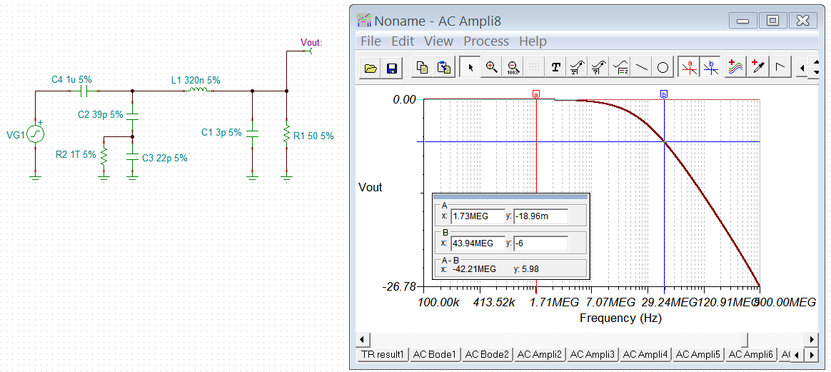
    BTW, with 50Ohm load instead of 1TOhm, you essentially de-Que the output circuit, though this is not the best way to de-Que the circuit. With 50ohm load, you also will attenuate the input signal significantly. In other words, if you run transient simulation, you input signal is going to attenuate approx -24dB from 1Vp-p at 162.45MHz. 

    Best,

    Raymond

  • Hi Pavel,

    as Raymond already mentioned, the simulation was done in TINA-TI. Yes, the internal resistance of VG1 can be modified:

    I also assumed a range of 90ms...100ms, first, like Raymond did. But then I realized that it actually is 900ns...1000ns :-)

    TINA-TI also shows a beating when the time window is set to 900ns...1000ns:

    Only when you give the simulation enough time to fully settle, the amplitude becomes constant and the beating can no longer be seen. The beating comes from the extreme sharp resonance of LC-circuit, as Raymond already stated.

    Kai

  • Hi Kai and Raymond,

    First of all, thank you for feedbacks.

    Here is definition of the linear circuit, taken from Wikipedia en.wikipedia.org/.../Linear_circuit:

    linear circuit is an electronic circuit which obeys the superposition principle.[1][2][3] This means that the output of the circuit F(x) when a linear combination of signals ax1(t) + bx2(t) is applied to it is equal to the linear combination of the outputs due to the signals x1(t) and x2(t) applied separately:

    In other words the shape of signal at output of a linear system must be the same as stimuli signal. The stimuli signal is pure sinusoide, whereas output - not. How can you explain this violation of the fundamental law of the circuit theory ?
    BTW I measured output between 9900 and 10000ns. The "beating"idn't decrease with respect to 900 ... 1000ns range.
    Sincerely,
    Pavel.
    vout_900_1000ns.pdfvout_9900_10000ns.pdf
  • Hi Pavel,

    but the stimulus is no pure sine. A mathematical sine is always there and has never started and will never end. In real life working with such a pure sine is impossible. You will always have to start the sine by starting the simulation of turning on the signal generator. According to Monsieur Fourier this is synonymous with having a whole spectrum of sine waves :-)

    Kai

  • Hi Pavel,

    Q: How can you explain this violation of the fundamental law of the circuit theory?

    I did not explain clearly other day about your question. Yes, your have a linear circuit. However, the behavior of Q is nonlinear. In LC circuit in an open loop system, Q is caused by double poles that are on top of each other. 

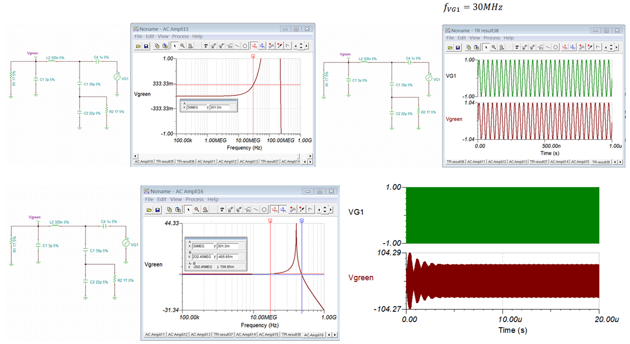
    The Q behavior is very broad. From frequency 30MHz onward up to 232MHz, the Q value is above 0dB as shown in the image below. That is why you are observing the multiple sinusoidal frequencies and amplitudes in your 9.9usec to 10.00 usec. This is a very short damping period.  

    Because your resistance is so high at 1TOhm, which it behaves like an open circuit. Once the oscillation starts, it will keep oscillating as if it is in a LC tank circuit (0.32uH with 3p+14p or 68MHz). The LC characteristic frequency of the circuit is 1/(2*pi*sqrt(LC)) = 162.44MHz. So it will take a long time to damp out, and it will not damp out if sinusoidal signal is applied at the input continuously (also look at the signal amplitude at 20usec). 

    On the right corner of the capture, the Q at 30MHz is 333.33mdB or 10^(0.333/20)=1.04Vp-p, shown on the plot on the right corner. That is a single frequency. If you inject at 162.45MHz, sum of these osc. frequencies start to interact with different frequencies and amplitude, because of the gain peaking or Q. 

    If you have other questions, please let us know. 

    Best,

    Raymond

  • Hi Pavel,

    I hope that we have answered your questions. I am going to close this inquiry. If you have additional questions, you are still able to post on the thread, or open a new one. 

    Best,

    Raymond