This thread has been locked.

If you have a related question, please click the "Ask a related question" button in the top right corner. The newly created question will be automatically linked to this question.

PGA281: Error Flag Detection - Unknown Reason

Part Number: PGA281

Hi ,

I am using PGA281 where its input stage supply is 10 V single ended (i.e VSP=10 V & VSN=0V) and

Output stage supply is 3.3V (i.e VSOP=3.3 V & VSON=0V) & Logic supply is 3.3V (Different power  from output stage supply).

Question: when trying to read the sensor output PGA error Flag get set?

Steps Followed:

1. We checked and make sure that all the power supplies (input,output and digital) are within limits

2. For the problem to be identified, we followed Figure 44, mentioned in the datasheet. (attached image for your reference)

3. Isolated Each section individually, input first and output next and both. The error Flag is still high.

4. I referred some of the posts in the forum and made decision that PGA281 IC might be damaged, so replaced with new IC

5.At first time, I was able to read the sensor output (Error Flag - low). and from Next time  onwards, the Error Flag becomes high, unable to read the sensor output.

Appreciate your advise as well as Help at the earliest !! Thanks in Advance.

Thanks and Regards,

Sarath Kumar C.

  • HI Sarath,

    Do you have a complete schematic of the PGA281 showing the differential input signal voltage, the absolute voltage of IN-N and IN-P pins with respect to GND and the voltage supplies?  Please let us know the gain settings desired and the digital state (low or High) of G0-G4 when the issue occurs.

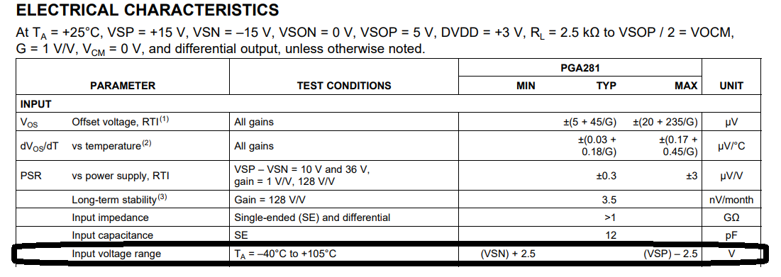
    You have mentioned that the device is powered with unipolar VSN=0V and VSP=10V supply.  Please keep in mind that the IN-N absolute voltage and the IN-P absolute voltage have to be at least 2.5V from the supply rails, therefore the minimum voltage for IN-N is +2.5V on a single ended measurement.  If you wish to perform single-ended measurements referenced to GND, with the negative input IN-N set at GND, the device will require bipolar supplies, or at least a negative supply of VSN < -2.5V.

    The image attached on your post above does not display, was this image showing Figure 44 or other?  if other figure, please re-post.

    Many Thanks,

    Kind Regards,

    Luis

  • Hi Luis,

    Thanks for your reply.

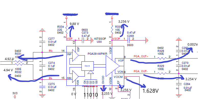
    Here by attached the schematics showing voltages measured. The desired gain settings are 176 with setting the bits [G4-G0]=11010. Gain settings is verified

    The image i was referred in previous thread is Figure 44 of PGA281 datasheet.

    Looking forward for your reply,

    Thanks and Regards,

    Sarath Kumar C

  • Hi Sarath,

    What is the max differential voltage expected from the sensor?

    The schematic above shows the PGA281 set on a gain of 176V/V with G4-G0 11010 as you have described.

    The differential input voltage shown on schematic above is 4.92V-4.94V = -20mV; the ideal differential output for this input would be about 176V/V*(-0.020V) = -3.52V differential output. 

    However, the ideal -3.52V differential output is outside of range of the amplifier given you have VSOP=3.3V and VSON = GND; where the max output differential voltage range allowed is +3.2V and -3.2V (100mV from the output stage supplies). 

    Can you reduce the gain to 128V/V or 64V/V and let me know if this resolves the issue?

    Thanks and Regards,

    Luis

  • Hi Luis,

    The maximum expected differential voltage from the sensor is 11 mV. But in this case, we are getting more voltage. We are seeing this issue with board specific.

    When we reduced the gain, the issue is resolved..

    Thanks and Regards,

    Sarath Kumar C

  • Hi Sarath,

    Thanks for letting us know.  Glad to hear the issue was resolved.

    Kind Regards,

    Luis