This thread has been locked.

If you have a related question, please click the "Ask a related question" button in the top right corner. The newly created question will be automatically linked to this question.

About small input bias offset voltage Op Amps (chopper noise).

Other Parts Discussed in Thread: OPA189, OPA388, OPA187, OPA392, OPA376, OPA191, OPA192

Thank you for your support.

I'm looking for an operational amplifier for input offset voltage is few micro voltage (for example, 5 to 10 micro voltage)..
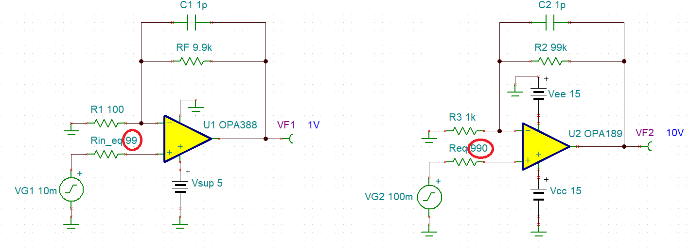
We are considering using the sensor signal output with a voltage follower circuit or a gain of about 100 times amp circuit.

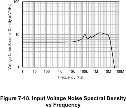
Q1: Basically, with a chopper type operational amplifier, I think that chopper noise is generated from the operational amplifier output voltage every several tens to several hundreds of kHz. This is a problem when used with a voltage follower, is there a way to remove the chopper noise?
Q2: Will the above chopper noise be multiplied by the gain, that is, several hundred times, if the operational amplifier is set with a gain of about 100 times?
Q3: If TI have an operational amplifier with an input offset voltage of severalmicro voltage and an fT of about 200kHz that does not generate chopper noise (for example zero dorift type? or auto zero type?), would you please introduce it?

Regards.

  • The OPA189 datasheet says:

    8.3.3 Input Bias Current Clock Feedthrough

    Zero-drift amplifiers such as the OPAx189 use switching on the inputs to correct for the intrinsic offset and drift of the amplifier. Charge injection from the integrated switches on the inputs can introduce short transients in the input bias current of the amplifier. The extremely short duration of these pulses prevents the pulses from amplifying, however the pulses may be coupled to the output of the amplifier through the feedback network. The most effective method to prevent transients in the input bias current from producing additional noise at the amplifier output is to use a low-pass filter such as an RC network.

    I can guess what the switching frequency is, but there is also noise at higher frequencies:

    (The OPA388 datasheet says it has no aliasing or flicker noise, but its voltage noise spectral density diagram cuts off at 100 kHz …)

    Do you need 200 kHz after the ×100 amplification?

    In practice, you need to care about other noise sources. See, for example, sections 8.3.8 and 8.3.9 of the OPA189 datasheet, and the Precision Labs videos.

  • Hi,

    what is your source resistance? I ask because applications with large source resistance do not necessarily profit from a chopper amplifier:

    Kai

  • Below please see my answers:

    Q1. The chopper noise comes from the input current spikes generated by closing/opening of the front-end switches at the chopper op amp input terminals. In a follower configuration there is no conversion of the current spikes into voltage spikes BUT any source resistance and/or gain resistors provide the way for the commutation of the IB spikes into voltage spikes.  Therefore, in order to minimize their effect on magnitude of the error, one needs to balance the input impedance at each input terminal by adding equivalent resistors, Rin_eq=RF||R1 and Req=R2||R3 - see below.

    Low voltage (5V) chopper OPA388 (max Vos of +/-5uV, GBW 10MHz), high voltage (36V) choppers OPA189 (+/-3uV, 14MHz) or OPA187 (+/-10uV, 550kHz) may be your best choice - see below.

    Q2. Once the chopper current noise gets converted across the resistor into the input voltage noise, its rms error adds to Vos and gets amplify to the output by the circuit's close-loop gain - for this reason it's important to match input impedance at each input terminal to minimize the input error.

    Q3. TI lowest offset non-chopper amplifiers:

    5V amplifiers: OPA376 (Max Vos of +/-25uV, GBW of 5.5MHz) and soon to be introduced RRIO OPA392 (+/-25uV, 13MHz) - samples available,

    36V amplifiers: RRIO OPA191 (max Vos of +/-25uV, GBW of 2.5MHz) and RRIO OPA192 (max Vos of +/-25uV, GBW of 10MHz).