This thread has been locked.

If you have a related question, please click the "Ask a related question" button in the top right corner. The newly created question will be automatically linked to this question.

OPA547: Comparison between inverting and non-inverting configuration

Part Number: OPA547
Other Parts Discussed in Thread: TINA-TI

Hi All,

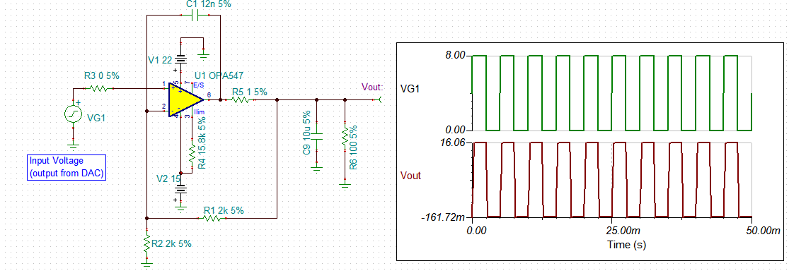
I am using OPA547 to generate a voltage source using a DAC. My DAC feeds a voltage to OPA547 which is currently used in non-inverting configuration. OPA547 multiplies it with a fixed gain and gives the output voltage. 

I read some application notes which mention about how OPAMP stability gets affected by capacitive load. They mention about using a resistor in series at the OPA547 output to improve stability of the overall system.

I would like to understand should i keep the circuit same or should i change the OPA547 to an inverting configuration.

It will be good if someone can answer the following questions,

- Does capacitive load affect both inverting and non-inverting configuration OPAMP in the same way?

- Which configuration is preferred for better stability and less heat dissipation from the OPAMP?

- Will changing my circuit to an inverting configuration improve overall stability?

- How effective is adding a series resistor at output of OPA547 in improving stability?

- How do i arrive at the right value of series resistor for my circuit?

Regards

Ayusman


  • Hello Ayusman,

    Regarding your questions:

    - Does capacitive load affect both inverting and non-inverting configuration OPAMP in the same way?

    The noise gain (the gain as seen form the non-inverting input to output) of the an op amp will be different when used in the non-inverting mode vrs the inverting mode. That is because the inverting gain is ideally G- = -RF/RI, and the non-inverting gain is G+ = 1 +(RF/RI). Therefore, the ratio of RF to RI will be different for the two configuration using the same closed-loop gain, G+ = |-G-|. The gain and phase responses across frequency will be different and can affect whether one configuration is less or more stable than the other.

    - Which configuration is preferred for better stability and less heat dissipation from the OPAMP?

    Since most TI op amps, including the OPA547, are specified as unity gain stable they should be when the output is driving a resistive load without stability problems. If the load becomes significantly capacitive, then that is most often the case where the phase margin degrades to the point where the op amp becomes unstable. In that case, the op amp circuit can be stabilized externally. But the ac characteristics such as bandwidth will be impacted by compensation.

    - Will changing my circuit to an inverting configuration improve overall stability?

    There may be some advantage to using the inverting configuration over the non-inverting configuration at very low gains such as G = 1 V/V. That is because the inverting configuration has higher noise gain (2 V/V) than the non-inverting configuration (1 V/V). But in general, if the stability is marginal for one, it is probably going to be an issue for the other. 

    - How effective is adding a series resistor at output of OPA547 in improving stability?

    The addition of a small series output resistor, which we refer to as Riso (isolation), can have a profound effect on improving the phase margin helping assure stability. A matter of ohms of Riso can make the difference between instability and total stability.

    - How do i arrive at the right value of series resistor for my circuit?

    See TI's Precision Labs - Op amps series on stability:

    training.ti.com/ti-precision-labs-op-amps-stability-introduction

    We can always assist you as well.

    Regards, Thomas

    Precision Amplifiers Applications Engineering

  • Hi Thomas,

    Thanks for your reply. It helped me understand more. However I am still confused between should I go for inverting configuration or keep my current circuit as is. I have thus attached my simulation file which I have used to simulate in TINA-TI. Can you please have a look at it and let me know your suggestions. The input VS1 in the circuit is a fixed voltage in the range of 0 to 15V. voltage_src_TI_analysys.TSC

    I will also go through the TI's link you have shared on op-amp stability to understand more.

    Regards

    Ayusman

  • Hi Ayusman,

    I made some changes in your circuit, and see if it will meet your need. The unity gain BW is configured at 6.1kHz with phase margin approx. 68.4 degree. 

    /cfs-file/__key/communityserver-discussions-components-files/14/voltage_5F00_src_5F00_TI_5F00_analysys-11172020.TSC

    BTW, the gain of the circuit is 2, therefore, your input can only be in the range of 0-10Vdc (V+ is 22Vdc), not 0-15Vdc, unless you increase the positive rail voltage above 30V and lower your negative voltage rail. You can use single supply configuration in the circuit.  

    Best,

    Raymond

  • Hi Raymond,

    Thanks for the suggestions. We had given the positive rail as +22 and negative rail -15V. So we believe input would be able to go from 0-15Vdc. Can you please confirm if our understanding is correct.

    Regards

    Ayusman

  • Hello Ayusman,

    Yes, using the +22 V/ -15 V supply arrangement should allow the OPA547 to easily accommodate a 0 to +15 V output voltage range.

    Regards, Thomas

    Precision Amplifiers Applications