Other Parts Discussed in Thread: INA302,
I am considering using the INA 300
What I want to use it for is to sense across a MOSFET drain / source to detect that it has gone out of saturation or overloaded. The 250mV detection limit matches quite well to my requirements. Obviously where a MOSFET differs from a resistor is that it can be off, which is where my questions are heading.
Anyway one point in the data sheet.
In the absolute maximum ratings it has:
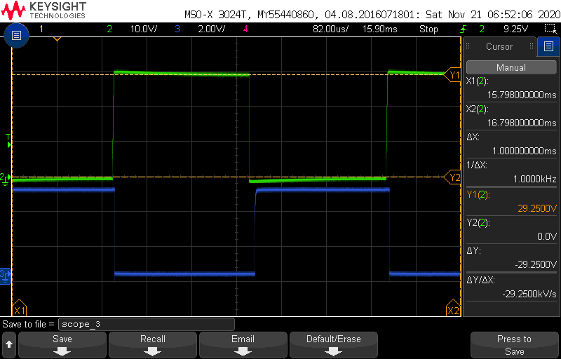
So I would expect no damage when the MOSFET is off as VDS will never exceed 40V, we only have 29V max. Good so far. However, note 1 states I can’t expect it to function at these limits.
So, in the electrical characteristics.
Our supply range is about 20 to 29V so Vcm is satisfied. However the differential input voltage is a problem. Now, I expect that the writers intended to indicate that the device can only have the threshold set between 0 and 250mV. Obviously, if the threshold is 250mV, then we must expect the device to function correctly with the Differential input voltage exceeding 250mV or the device would make no sense, else how would the ALERT be signalled with the input was at 275 mV or a mere 10% overload condition? However, by definition TI has stated they do not even imply it will work (again refer to note 1 above).
So can you verify please if having a 29V differential input voltage is acceptable and will not cause erroneous behaviour in the device?
Many Thanks
Calex