This thread has been locked.

If you have a related question, please click the "Ask a related question" button in the top right corner. The newly created question will be automatically linked to this question.

OPA547: OPA547 OP-AMP current limit (Ilim) resistor calculation

Part Number: OPA547
Other Parts Discussed in Thread: TINA-TI

Hi,

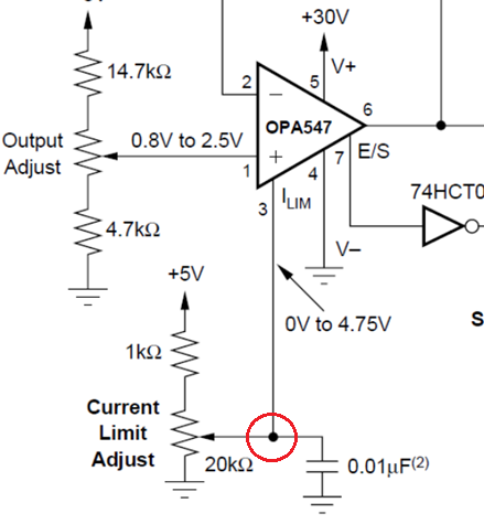
I am using OPA547 OP-AMP for our new project and I am using the below approach for limiting the current:

I am using a 100K digital potentiometer instead of a variable resistor to control the current limit through software. And I have simulated the same circuit with Tina-Ti and LT Spice which is working fine.

Please see the below the Tina-Ti simulation circuit:

As per the above simulation circuit, 250mA current limit can be achieved by setting the current limit resistor value to 17.3K and 21mA current limit can be achieved by setting the current limit resistor value to 31.5K.

But I need to derive an equation to calculate the current limit resistor value for different current limit options as we are using this OP-AMP for a programmable power supply application.

Could you please help me to derive the current limit resistor equation for the above current limit option which will be used our software team to program the current limit user input?

Regards

Vysakh

  • Hi Vysakh,

    Could you please help me to derive the current limit resistor equation for the above current limit option which will be used our software team to program the current limit user input?

    DAC method to control current limit is shown in Figure 3 (p.9 of the datasheet), see the capture image below. 

    If V- is 0V or GND, then Vdac = 0 +4.75V - 31.6kOhm*I_lim/5000. 

    For instance, I_limit=375mA, Vdac = 4.75V - 31.6kOhm*0.375/5000 = 2.38V, which it matches the figure in the label above. 

    I_limit=250mA, Vdac = 4.75 - 31.6kOhm*0.250/5000 = 3.17V, assume V- = 0 or GND

    I_limit=21mA, Vdac = 4.75 - 31.6kOhm*0.021/5000 = 4.617V, assume V- = 0 or GND

    Your image was not loaded properly, so I am unable to see your schematic. 

    In the future, use the icon circled in red to upload an image file, use the icon circled in green to upload a standard file. 

    If you have other questions, please let us know.

    Best,

    Raymond

  • Hi Raymond,

    I am not using the above technique for the current limit function. I have attached the current limit technique which i have used in my design and the Tina-Ti circuit used to simulate the same. I need to derive an equation for the current limit resistor for below circuit.

     PPSU1_0V to 16V_250mA_02102020_08 30 PM.TSC

    Best Regards

    Vysakh

  • Hi Vysakh,

    exactly the same considerations and formulas apply :-)

    Kai

  • Hi Vysakh,

    As Kai pointed out, you need to configure a voltage shown at the circled node for the following I_limit conditions. 

    I_limit=250mA, Vdc = 4.75 - 31.6kOhm*0.250/5000 = 3.17V

    I_limit=21mA, Vdc = 4.75 - 31.6kOhm*0.021/5000 = 4.617V


    If you have additional questions, please let us know. 

    Best,

    Raymond

  • Hi Kai,

    The exact changes made on the current limit circuit is shown in the below image:

    I am using a +10.5V & -10.5V for V+ & V- supply respectively. I am using an external 5V reference with a constant resistor value of 4.99K & a 100k digital potentiometer for controlling the current limit value. I need to derive an equation for calculating the digital potentiometer set resistor value for different current limit values which will be used by our software team to implement the programmable current limit feature.

    Could you please go through the Tina-Ti simulation file attached in the above post and help me to derive the equation for the same?

    Best Regards

    Vysakh

  • Hi Vysakh,

    Here is how it is calculated. 

    (5V - (-10.5V))/(R1 + R2 +R3) = (Vlim - (-10.5V))/R3, where R2 + R3 = 100kOhm

    15.5V/104.99k = (3.17V + 10.5)/R3 and calculate R3 = 92.594kOhm, see the attached simulation. (The current flow from 5V to -10.5V are identical and apply Ohm's law). 

    /cfs-file/__key/communityserver-discussions-components-files/14/OPA547-Voltage-divider.TSC

    If you have additional questions, please let us know. 

    Best,

    Raymond

  • Hi Raymond,

    I have already tried these equation. But there is an internal resistor (31.6k) and a 4.75V source inside the OP-AMP ILIM pin which is coming into picture for the calculation. So, I separately simulated that with LTspice simulator and found that the above calculation is getting affected by the internal  resistor (31.6k) and a 4.75V source. Please find the LT spice simulated circuitry below:

    As per the above diagram, the R1 & V1 is the OPA547 internal 4.75 voltage source and 31.6k resistor and R3 & R4 is acting as the 100k digital potentiometer and the ILIM marked point is the OPA547 current limit pin. As shown in the figure, the calculation suggested by you is matching only if the internal 31.6k resistor connection is disconnected from the ILIM pin. The values are getting changed when the OPA547 internal 4.75 voltage source and 31.6k resistor are connected.

    Calculation example:

    R3 calculated with 250mA current limit (With the above calculation):

    (5V - (-10.5V)/(R1 + R2 +R3) = (Vlim - (-10.5V)/R3, where R2 + R3 = 100kOhm & R1 + R2 + R3 = 104.99kOhm

    R3 = (3.17 * 104.99) / 15.5 = 21.47k

    As per the above calculation, a 21.47k resistor value should be set to achieve the 250mA current limit. But the Tina-Ti simulation shows that the 250mA can be achieved with a 17.3k resistor value. This difference is occurring because of the OPA547 internal circuitry effect.

    Best Regards

    Vysakh

  • submitted by mistake. 

  • Hi Vysakh,

    I see your problems are. You need to connect the potentiometer directly to pin3 as the diagram is shown on the resistor method. Or you use DAC method. 4.75Vdc is internal to OPA547. Can you connect in the following manner? 

    We still have to the following equation. With resistor divider method, Rcl is calculated to be 5000*4.75/0.25 - 31.6kOhm = 63.4kOhm. 

    /cfs-file/__key/communityserver-discussions-components-files/14/6201.OPA547-Voltage-divider-11262020.TSC

    If you have additional questions, please let me know. 

    Best,

    Raymond