This thread has been locked.

If you have a related question, please click the "Ask a related question" button in the top right corner. The newly created question will be automatically linked to this question.

AMC1200: Output fluctuations during EMI/EMC test

Part Number: AMC1200
Other Parts Discussed in Thread: , TIDA-00835, AMC1301, AMC1300, ISO224

Hi

I am using AMC1200 for measurement of DC voltages upto ±1000V. The final output goes to the differential ADC channel.

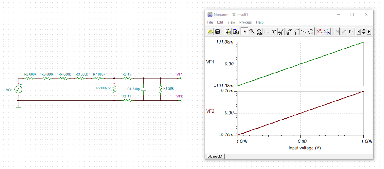
Please refer to the attached schematic.

I need to attenuate the output of AMC1200 since the allowed ADC input range is ±500mV.

During normal operation, the output is uniform without any noise or fluctuations.

But, during RS test (Radiated Susceptibilty) the output of AMC1200 gets disturbed. The final output of the circuit fluctuates by around 1-2mV which translates to 5-10VDC in terms of measured Input Voltage.

I have monitored the input and output signals of AMC1200 and found that the input signal does not vary. Only the output signal fluctuates.

I have also monitored the input and output VDD signals and there is no variation there also.

What could be the cause of this kind of fluctuations and how to eliminate it?

AMC1200

Thanks,

Avik Bhowmik

  • Hi Avik,

    I see several issues in your circuit:

    1. You violate the common mode input voltage range of -0.16V...VDD1.

    2. The AMC1200 is designed for current measurement across low ohmic shunt resistance. But your R6 is rather high. This decreases the balance of input circuitry and results in decreased common mode rejection.

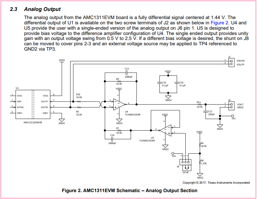
    3. The AMC1200 provides true differential output signalling and needs to be terminated symmetrically. But you terminate it highly unsymmetrically and too low ohmically. See the AMC1200EVM for a suited output circuit:

    Kai

  • Hi Kai

    Thanks for your reply.

    1. You violate the common mode input voltage range of -0.16V...VDD1.

    Since, the VINN pin is referenced with respect to GND1 I don't think common mode input voltage range should be an issue here. 

    Also, a similar design has been suggested for isolated voltage sensing in Application note TIDA-00835. Though the reference design is based on AMC1301, but the same design should apply to AMC1200 too.

    Could you please elaborate more on this point.


    2. The AMC1200 is designed for current measurement across low ohmic shunt resistance. But your R6 is rather high. This decreases the balance of input circuitry and results in decreased common mode rejection.

    In TIDA00835, the shunt resistor in voltage divider circuit is 649ohm.

    iso voltage

    The Input resistance of AMC1200 is 28kohm which is quite large as compared to 666ohm.

    Do you think R6 needs to be still lower than 666ohm or what could be the appropriate value?


    3. The AMC1200 provides true differential output signalling and needs to be terminated symmetrically. But you terminate it highly unsymmetrically and too low ohmically. See the AMC1200EVM for a suited output circuit:

    Like I mentioned earlier I need to attenuate the output to suit my sigma-delta ADC differential input range. And I need to avoid using op-amps for attenuation for several reasons like less PCB footprint, need differential signal, lower cost of circuit.

    What other option is there to attenuate the output signal? Will higher values of resistors do the job?


    Do suggest what other modifications need to be done for faithful operation?

    Also please suggest proper values of decoupling and filter capacitors for this application.


    Thanks,

    Avik Bhowmik

  • Hi Avik,

    The AMC1200 and AMC1300/AMC1301 have slightly different input structures but they all have a relatively low input impedance as Kai pointed out.  Your 666.66 ohms is in parallel with the 28k Zin which makes it look more like a ~651 ohm resistor.  That alone could account for some mV's of error in the output.  You could also reduce the bandwidth of your input filter (make C1 10nF for example). 

    You might also look into the ISO224 device which was designed for voltage sensing applications and has a significantly higher input impedance.  That part has a single ended +/-12V input range and a similar output differential structure to the AMC1200.  You could do the attenuation through a fully differential amplifier configuration to accomodate the Vcm of your ADC.

  • Hi Avik,

    1.

    VF1 (or VINP of AMC1200) definitely exceeds the specified common mode input voltage range of AMC1200 of -0.16V...VDD1. Please look into the datasheet.

    2. Rin=28k is only a tyical specification and can widely vary from chip to chip. Referring the increase of error due to your R6 see section 8.2.2 of datasheet. And yes, I would decrease R6.

    3. Whatever you do at the output of AMC1200, do it symmetrically. Your scheme arround R9, R10, R13 violates this design practise and introduces imbalance which results in a ruined common mode rejection.

    Kai