This thread has been locked.

If you have a related question, please click the "Ask a related question" button in the top right corner. The newly created question will be automatically linked to this question.

OPA4140: Amplifier circuit support required on redesigning/optimizing

Part Number: OPA4140
Other Parts Discussed in Thread: DAC7564

As a part of my new project I need to redesign UV LED driving circuit. Here I am using TI’s AM335x processor and using the SPI I have connected one DAC – LTC2668-12. The DAC output is going to the UV LED - NSHU591C. The specification of UV LED is given below.

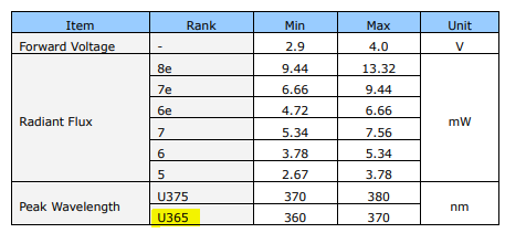
(Highlighted one is using).

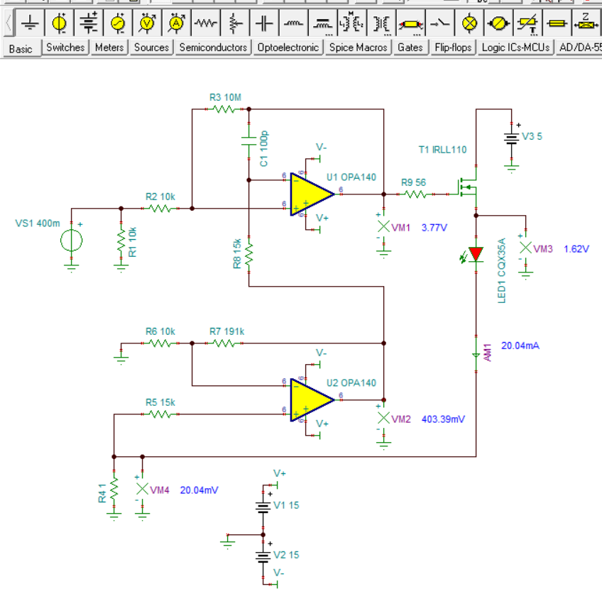
The DAC output (set to 0.068V) is connected to OpAmp (OPA4140) circuit and it is used for constant current sourcing (correct me if my understanding is wrong). The circuit is given below.

The UV LED’s cathode is connected to the non-inverting terminal of the amplifier B for current measuring.

DAC_VOUT1 – DAC channel 1 output.

LED1_A – UV LED Anode

LED1_K – UV LED Cathode

I have some queries on this.

  1. In the first OpAmp and MOSFET configuration how the current is controlling.
  2. Currently in the circuit a 12-bit 16channel DAC is using, I have a plan to replace the DAC with TI’s DAC7564. Will it compatible with the further circuit or suggest some cheaper DAC having 4 channel and better accuracy.
  3. Is there any calculation for the above OpAmp configurations to find the output theoretically(not find in the datasheet)

Thanks

Sebastian

  • Hello Sebastian,

    Regarding your circuit questions; there is quite a bit going on in the circuit.

    1. In the first OpAmp and MOSFET configuration how the current is controlling.

      The DAC output voltage is applied to the U36A +In input via R357. The U36A output adjusts the level so that the output at U36B is equal to te DAC voltage, such that the U36A inverting and non-inverting are at approximately the same voltage. The Q10 MOSFET sources current to the LED load. The LED current flows through R364, the 1 Ohm current sense resistor. The voltage across R364 is sensed by U36B which gains up that voltage by about 20x. Then, the output voltage of U36B is applied to the U36A inverting input.

      2. Currently in the circuit a 12-bit 16channel DAC is using, I have a plan to replace the DAC with TI’s DAC7564. Will it compatible with the further circuit or suggest some cheaper DAC having 4 channel and better accuracy.

      We don't provide coverage for TI's DAC products here on the Precision Amplifiers e2e forum. I suggest posting an inquiry to the Converters e2e forum for the best assistance with such questions.

    2. Is there any calculation for the above OpAmp configurations to find the output theoretically(not find in the datasheet)

    This is not a straightforward inverting, or non-inverting op amp circuit and involves two feedback paths. With the resistor values shown the circuit produces a transconductance gain of about 50 mA/V, or 50 mS. Deriving the transfer function for this circuit would take time. I've included the TINA simulation circuit so that you can observe how the circuit operates and that should provide you some help in deriving the transfer function.

    OPA140_LED_driver_01.TSC

    Regards, Thomas

    Precision Amplifiers Applications Engineering

  • Hi Thomas,

    Thank you very much for your simple and brief explanation.

    I have one small query, why the value of R8 in the simulation is 191K instead of 15K. Any particular reason for that?

    Thanks & Regards,

    Sebastian

  • Hi Sebastian,

    I simply carried the R7, 191 k value on to R8 when I was setting up the TINA schematic. TINA uses the last resistor value you enter if you don't change it to another value for the next resistors. Fortunately, having R8 set to 191 k, vs the correct 15 k, only affects the ac response. The dc levels stay the same as a new simulation shows with R8 is 15 k.

    Regards, Thomas

    Precision Amplifiers Applications Engineering

  • Hi Thomas,

    Thanks for your quick response and this information, your answer give me a good understanding on the circuitry. 

    Regards,

    Sebastian