This thread has been locked.

If you have a related question, please click the "Ask a related question" button in the top right corner. The newly created question will be automatically linked to this question.

INA1620: & OPA1622 bias current implications

Part Number: INA1620
Other Parts Discussed in Thread: OPA1622, LM4562, TINA-TI, OPA827, OPA828

I am a little mystified as to how the high bias current of these devices interacts with resistances in the bias position and on the inverting input. Part of that is my lack of an EE background. The series resistance limitations are clear -- keep it under 10K.

It is common to put 47KΩ-100KΩ bias resistors at the non-inverting inputs of voltage followers, some with input impedances down to 30KΩ...the LM4562 is a good example with 72nA Ib...but I'm unsure of what amp characteristics would turn this common practice into a noise liability. IIRC, the OPA1622 and INA1620 are spec'd at 60KΩ Zin and ~1200nA Ib. 

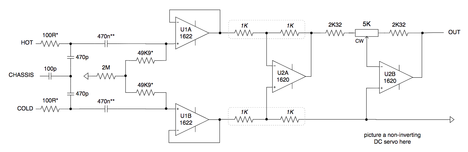
1) How would either device handle a three-amp unity gain instrumentation front end application (U1), with high bias resistance and low series resistance? Most sources are <100Ω but some could be 1KΩ to 2KΩ, with the associated small capacitances from reasonable lengths of good quality cabling. This isn't designed for guitar or bass (obviously not a FET front end), but that would be 5KΩ to 13KΩ. Curious how noisy these scenarios would become.

2) Does anything change significantly if Rf and Rg are added to U1, as in a typical high-gain IA, assuming Rf is something like 1KΩ to 2KΩ and U1 gains are anywhere from 4 to 100?

3) How would either device handle a less-than-10K variable resistor at an inverting input (U2B)? Significantly worse than, say, a somewhat precision BJT device with 10nA of bias current - or not?

U2B is a ±10dB trim, by the way.

Thanks!

  • Hi Jonah,

    why not running a TINA-TI simulation with the

    INA1620 TINA-TI Reference Design (Rev. A)

    ?

    Kai

  • There are a lot of subcircuits I have to simulate for the current project once I get a PC. I have a Mac but I don’t really want to attempt this in LTSpice because the models would all be for TI chips.

    I wonder if John Caldwell’s around...

  • Hi Jonah,

    two times the input bias current of OPA1622 times the 2M common mode resistance gives a worst case DC common mode voltage of 8.8V! So the OPA1622 isn't well suited for this kind of topology. In this situation I would take the TI's lowest noise audio FET-OPAmp OPA827.

    To decrease the noise at lowest audio frequencies, the 470n caps should be increased. This will lower the source impedance seen by the OPA1622 inputs and by this lower the noise.

    By the way, the 470n caps will ruin the common mode rejection at low audio frequencies as well because of their manufacturing tolerances and differing temperature and long term drifts. Differing cap impedances will cause a considerable imbalance and by this heavily lower the common mode rejection of your differential amplifier. It would be wise to massively increase the 470n caps, if highest common mode rejection is wished :-)

    Kai

  • Hi Jonah,

    Considering with your schematic, as Kai pointed out, OPA827 or OPA828 could be the recommendable opamps.

    While, I will prepare some simulation to see your concerns.

    Best regards,
    Iwata Etsuji