This thread has been locked.

If you have a related question, please click the "Ask a related question" button in the top right corner. The newly created question will be automatically linked to this question.

XTR117: Vreg out is not 5V

Part Number: XTR117
Other Parts Discussed in Thread: TINA-TI,

Hi,

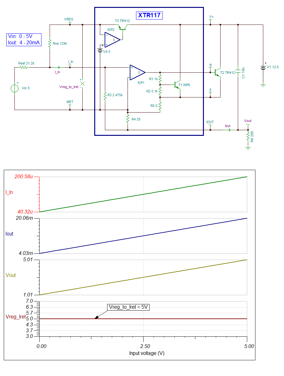
Could you please check if the circuit below works properly?

According to customer evaluation, when the output current is increased, the voltage of the 250Ω load saturates around 3.5V. At this time, the Vreg voltage also drops to 3.5V.
What's wrong?

Also, I tested it with TINA-TI. Vreg changes according to the output current, and it seems that Vreg is not a constant 5V voltage.

Ros=220k
Rset=20k
RL=250
Vs=10V
Vin =0 to 5V

Regards,
Hiroshi

  • Hello,

    It looks like the compliance voltage of the XTR117 is being violated. The voltage between V+ and Io needs to be 7.5V for the XTR117 to operate properly. Using a V+ of 10V, when Vout is at 3.5V only 6.5V is left across the transmitter. Potential solutions would be to increase the supply voltage or decrease the 250ohm load. The ideal components used to create the behavioral XTR117 model don't reflect the compliance voltage requirements. 

    Also, VREG is measured with respect to the Iret pin of the XTR117. A "Voltage Meter" should be placed in TINA instead of a "Voltage Pin" which is measured with respect to ground. 

  • HI Hitoshi,

    Please keep in mind that the attached TINA simulation is not a TI official model and it only mimics an idealized XTR117 transfer function.  Therefore the attached simulation does not model the non-ideal behavior of the XTR117 such as offset, frequency response/dynamic response, noise, span error, supply/compliance behavior.  However, the attached simulation is still  useful to check the values of Ros and Rset and quickly verify the transfer function.

    There are a few circuit changes required:

    1) In order for the XTR117 device to support 4mA to 20mA output accepting a 0V to 5V input, the correct resistor values are:

    Ros=125kOhm = 124kOhm

    Rset = 31.25kOhm = ~31.2k Ohm

    2) The minimum compliance voltage for XTR117 is ~7.5V per page 6 of the datasheet.  With a 250-ohm RLOAD and 20mA current, this results at +5V output at RLOAD when IOUT=20mA.  Therefore the minimum loop supply will have to be at least +5V+7.5V>+12.5V to ensure the XTR117 has enough compliance.  Please suggest a minimum supply that exceed VS > ~ 12.5V for this 250Ohm load resistor.

    3) The XTR117  recommends a bypass capacitor Cout of about 10nF between Io and V+ pins.

    3)  This is a 2-wire current transmitter, where IRET floats or moves with respect to the loop supply.

    The IRET is the local ground for the XTR117,and the VREG pin offers a 5V output with respect to the IRET pin.  See attached simulation where the VREG is +5V with respect to IRET.

    Please review/consult the following link with information about 2-wire current loop transmitters. Please look into 2-wire FAQs.

    [FAQ] Designing with 4-20mA current loop transmitters (XTRs): FAQ links

    Thank you and Regards,

    Luis

    XTR117_forum_12-14-20b.TSC

  • Hi Luis,

    Thank you for the detailed explanation.
    I reported to the customer and confirmed that they understood.

    Best Regards,
    Hiroshi

  • Hi Katlynne,

    Thank you for your reply.

    I and my customer understood.
    Thank you again.

    Best Regards,

    Hiroshima