This thread has been locked.

If you have a related question, please click the "Ask a related question" button in the top right corner. The newly created question will be automatically linked to this question.

XTR106: Linearization for bridge with unknown bridge nonlinearity polarity.

Part Number: XTR106

Hi Team,

In data sheet, figure 3d can be used for bridges with unknown bridge nonlinearity polarity. 

Does Rx and Ry should always be fixed at 100Kohm and 15Kohm? And the two resistors should be both on the circuit for unknown polarity?

I'm a little bit confusing about how to choose the Rx  and Ry value.  "Open RX for negative bridge nonlinearity."

"Open RY for positive bridge nonlinearity."

The description abobe seems conflict with the unknown polarity. If I have known the polarity, I will follow the circuit 3a or 3b. And even in positive situation what's the relationship between Rx value and liberalization compensation. Please help clarify the meanings.

Best Regards,

Tess Chen

  • Hi Tess,

    do you know the nonlinearity of your sensor? Is it specified in the datasheet of sensor?

    Kai

  • Hi Kai,

    I don't know the nonlinearity of sensor. And I am confusing about what configuration I need follow, figure 3a, 3b or 3d? 

  • Hi Tess,

    what says the datasheet of sensor?

    Kai

  • Hello Chen,

    The XTR106 corrects positive or negative second-order nonlinearity. The Linearization section of the XTR106 datasheet explains that signal-dependent variation of the excitation voltage adds a second-order term to the transfer function. This second order term can be adjusted to correct for bridge non linearity. As shown on the example of Figure 3, both the % non-linearity error of the sensor and polarity of the non-linearity need to be known.

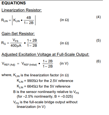
    The linearity resistor is calculated using the KLIN factor (given in the datasheet KLIN=9905 Ohms for 2.5V reference or KLIN=6645 Ohms for 5V reference), and factor “B” which is the sensor non-linearity relative to full-scale:

    For positive bridge nonlinearity (upward bow), Lin Polarity (pin 12) should be connected to IRET (pin 6) as shown in Figure 3a (where VREF increases with bridge output). To correct for negative nonlinearity (downward bow), connect Lin Polarity to VREG (pin 1) as shown in Figure 3b (VREF decreases with bridge output).

    To answer your question, Figure 3d shows a PCB layout where the user has the flexibility to un-populate either RX or RY depending on the sensor linearity error polarity. If no linearity correction is desired, in general you will use figure 3c, with pin 12, pin 11 and VREG connected together.  Alternatively, Figure 3d with the RX and RY resistors populated at the same time and RLIN = 0-ohm, is behaving exactly the same as figure 3c, performing no correction. The RX (100k) and RY (15k) resistive divider when populated is setting the Lin Polarity pin closer to the VREG or high potential, turning the current switch to essentially the same configuration shown on Figure 3c.

    In summary, the user is always required to know the polarity and linearity % error of the sensor to perform the linearity compensation and Calculate RLIN (resistor between VREG (pin 1) and pin 11), and tie pin 12 (Lin Polarity) either to IRET or VREG depending on the linearity polarity correction.

    Thank you and Regards,

    Luis

  • Hi Tess,

    I would like to know whether the sensor shows a nonlinearity which is worth to be linearized at all :-)

    Kai

  • Hi Luis,

    Thanks for the explanation. According to your words, I assume that in positive polarity situation, whether I follow 3a(short  PIN6 and PIN12 ) or 3d(Rx=100Kohm between PIN6 and PIN12) both correct and have no difference, right?

    Best Regards,

    Tess

  • Hi Tess,

    Yes, as shown on the figure 3d, if positive bridge non-linearity correction is required, the user will open RY and will be left with RX=100kohm between pin 6 and pin 12.  This essentially sets the Lin Polarity pin voltage to IRET, and is equivalent to the configuration on figure 3a for positive bridge non-linearity. The linearization resistor (Rlin) will have to be selected according to equation (4) on Figure 3.

    Thank you and Regards,

    Luis