A related question is a question created from another question. When the related question is created, it will be automatically linked to the original question.
If you have a related question, please click the "Ask a related question" button in the top right corner. The newly created question will be automatically linked to this question.
Part Number: LM393-N Other Parts Discussed in Thread: LM393
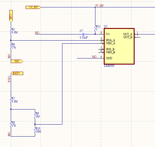
I want to make sure that the input impedance of the input pins is high enough that it won't be affected by the voltage divider circuit I have designed here in the attached snapshot.
Yes Sure..... I would like to install 0603 resistors hence I split the values accordingly. Please help me with suitable values. The powering points MC+ And MC- are at 530V maximum and I am controlling Precharge and Accumulator Isolation Relay with this circuit. LM393 should change logic levels at 90% of the Battery Voltage.
Depending on your desired resistor tolerance, I would suggest splitting R8 into resistances as close to a 2.45kOhm and a 24.54kOhm. (So maybe a 2.44kOhm and a 24.6kOhm?)
To maintain the 10/11 ratio of the voltage seen at the bottom of R7, the ~2.45kOhm should be placed on the top of the voltage divider and the ~24.54kOhm should be placed on the bottom of the divider and connected to GND.
The voltage across the ~24.54kOhm should feed the "NEG_A" input to the LM393.
Would you still like to implement external hysteresis?