This thread has been locked.

If you have a related question, please click the "Ask a related question" button in the top right corner. The newly created question will be automatically linked to this question.

INA282: Current Sensing circuit ,Accuracy 1mA

Part Number: INA282
Other Parts Discussed in Thread: INA210, INA302, INA240, INA190

Hello,

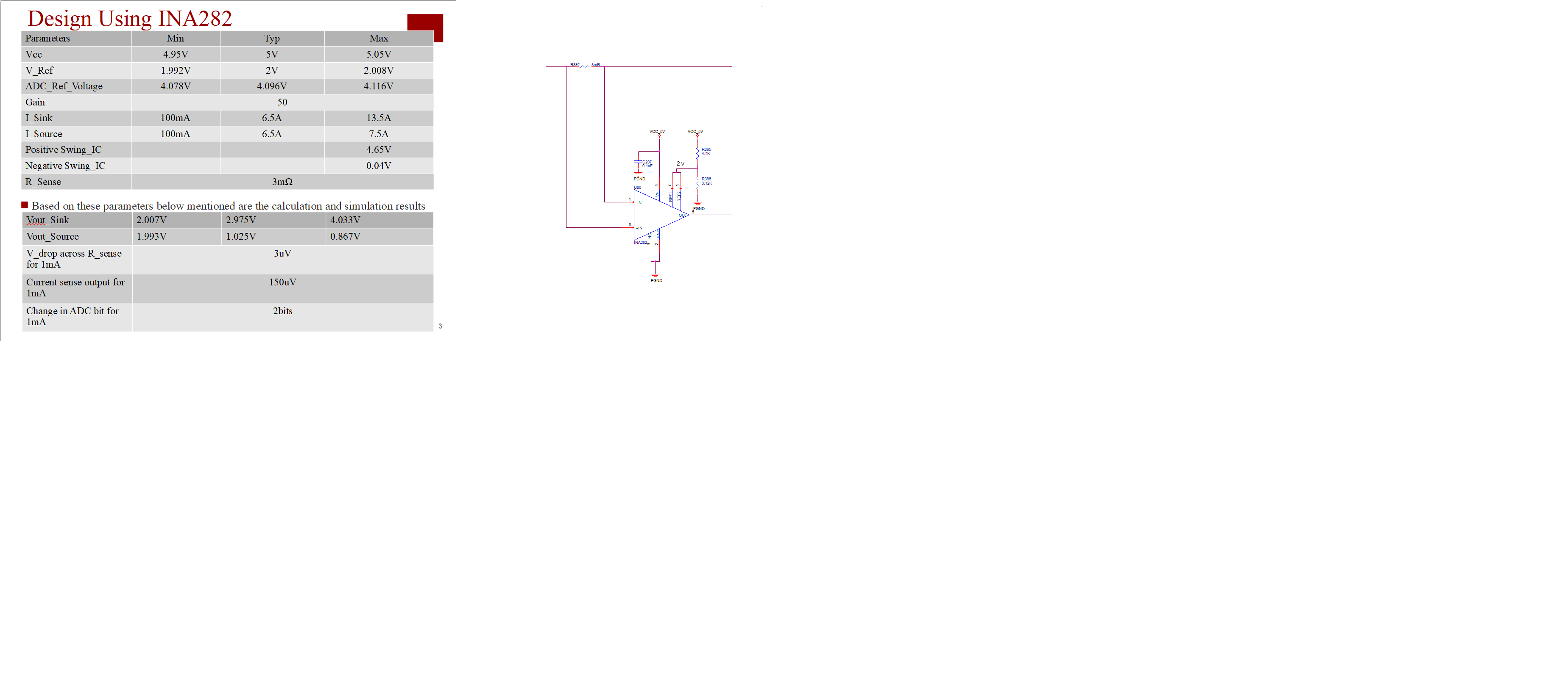
I am Using current INA282 Current sensor (Bi-Direction).

My Current range is from 100mA to 13.5A in one direction and in another direction the Current range is 100mA to 7.5A.

Voltage range is from 800mV to 70V on both the direction.

Supply voltage for the IC =5V


My ADC ref is 4.09V

I need to measure each 1mA current.

I am attaching my circuit and calculation.

Could you please let me know whether my circuit is ok or any better circuit can be used.

  • Hi Sebastian,

    what do you mean by

    I need to measure each 1mA current.

    I thought it is 100mA :-)

    Kai

  • Hey Tensil,

    Thanks for posting your question.

    I believe in order to achieve your 1% error tolerance, you will need to increase the shunt resistor or perform an offset calibration procedure.

    The INA282 can have a max input offset of ±70µV. At 100mA load current, the sense voltage is 0.1A*3mΩ = 300µV. Offset error alone is already 70/300 = 23.3%.

    In addition, the gain error of the INA282 can be a max ±1.4%, thus if using this device you would also need to perform a gain (two-point) calibration procedure which requires running a load of a known current value and reading the output.

    I would recommend using a bi-directional current sense amplifier device with better gain error like the INA190, INA210, INA240, or INA302 to remove the need for a gain calibration, although you will need to still either increase shunt resistor or perform a offset calibration to remove offset error.

    To learn more about calculating error consider watching our free training series here:

    Best,

    Peter

  • Thank you peter ,the tutorial was very helpful