This thread has been locked.

If you have a related question, please click the "Ask a related question" button in the top right corner. The newly created question will be automatically linked to this question.

INA225: power up INA225 with 10V and -5V power supply

Part Number: INA225

Hi team,

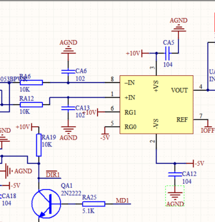
My customer wants to use the INA225 in the system. The schematic is as below.

We want to use the device with 10V and -5V power supply, the input signal common mode voltage is with -5V~10V(ref, IOFF is 0V). In my opinion, the structure should be fine. Do you have some suggestions about the schematic? Whether it's fine? What's the risks? Thanks.

  • Frank,

    You are able to split the supplies this way, and everything looks good with the setup. Digital pins look to be set validly, and the customer is referencing the device to 0V to swing between -5V/10V. 

    The one area of concern I did see is that the customer is using 10k resistors for the input filter. We typically advise that these resistors be <10Ω and the capacitor be sized appropriately to the cutoff value desired. This is because these resistors will alter the gain of the device, and increase error. You can looks at section 7.4.1 of the datasheet for more information on this. The section also provides formulae for calculating the additional error added by these resistors, but be aware that the internal resistors of the device are trimmed to each other, rather than an absolute value, and can fluctuate by up to 20% part to part. This is why we advocate against the use of this size of resistor.