This thread has been locked.

If you have a related question, please click the "Ask a related question" button in the top right corner. The newly created question will be automatically linked to this question.

INA260: Negative current measurement

Part Number: INA260

Hello,


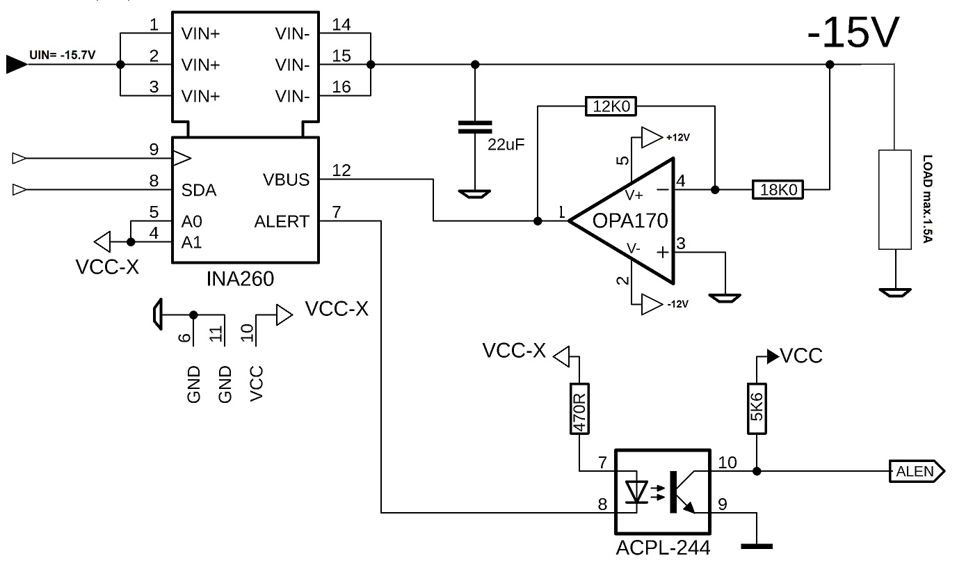
I have a problem with measuring negative currents. The INA260 works fine and I can read the I2C address.
But if I switch the -15.7V to this, the INA260 is destroyed and the VCC-X goes back to 3.2V.
What am I doing wrong?

With best regards

Wolfgang

  • Wolfgang,

    Thanks for choosing TI!

    The issue here is that you are violating the common mode of the device:

    While the device is capable of bidirectional current measurement, the pins may not drop more than 300mV below ground. From the diagram you are showing, you are subjecting the pins of the device to ~-15.7V, which is well over the 300mV, and it is damaging the device.

    You could try moving to the low side, so that the common mode of the device is closer to ground, but even then you must be careful to ensure that the common mode does not exceed the absolute maximums.

  • Hello Carolus,


    Thank you for the quick answer.
    I hadn't seen that, my mistake.
    Here is my suggestion for the circuit.
    Is that right?

    Please check!

    Regards

    Wolfgang

  • Wolfgang,

    Having a look at the schematic, I think this looks good. A few things I noticed during my review that I would pay attention to:

    - You may have to alter the R1 based on the power consumed by the resistor. 

    - You may want to adjust the value of the pull-up resistor R2 into the alert pin of the device. Not taking the VOM617 into account, you are currently driving nearly 8mA into the open drain. Our test limit as shown in the datasheet is 3mA, so you may want to reign this in a bit, and the absoulte maximum current allowed for all open drain pins of the device is 10mA. This seems rather close to the line when you could have more margin. 

    Let me know if you have any questions.  

  • Hello Carolus,


    Thank you very much for the hints.
    I changed the value from R2 to 1K2, then the current in the ALERT pin is only about 3.3mA.
    The power dissipation of R1 with 0.5W is okay for me!
    Thank you for your competent support and
    no further questions about this.

    Best Regards

    Wolfgang