This thread has been locked.

If you have a related question, please click the "Ask a related question" button in the top right corner. The newly created question will be automatically linked to this question.

TLV3201: TLV3201 Inverting Spice Model

Part Number: TLV3201
Other Parts Discussed in Thread: LM339

Hello,

I was reading the tread titled: TINA/Spice/TLV3201: TINA Spice model shows output inverting with large signal, and it looks like the Spice Model for the TLV3201 was either updating or going to get an update to reflect the use of ESD diodes in the part. Has this been completed because it seems that the models available on the TLV3201 web page still show inverting outputs, which would suggest the model hasn't been updated yet.

Additionally, in bench testing the TLV3201, it seems as though there is a current sensitivity to whether or not the output will exhibit an inversion result. When stimulating the negative input, no inversion result was seen regardless of overdrive polarity. When stimulating the positive input, no inversion was seen when over driving in the positive direction, but an inversion was seen when over driving the positive input in the negative direction (below the ground reference) with more than 5mA. Is this a function of how the ESD diodes are setup inside the part? Is it expected that there should be a current dependency and non-symmetrical results when looking for inversion events?

Is it possible to see the layout of the diodes inside the TLV3201, or is there another similar part in the family that has the same diode configuration?

Thank you!

Tyler

  • Hello Tyler,

    The new model has not been released yet. It is more complicated than the existing model and there were some issues to still be worked out.

    Pulling the inputs far below ground will cause malfunctions, as you have seen. When going negative, junctions that are not designed to conduct start conducting, which can lead to malfunctions.

    The Absolute Maximum describes the conditions where the device will not be damaged, but does not necessarily mean that the devices will function properly during that time. The device must be operated within the Recommended Operating Conditions for proper operation.

    At 5mA, you are going to be at or past -0.5V. The datasheet limit is -0.2V.

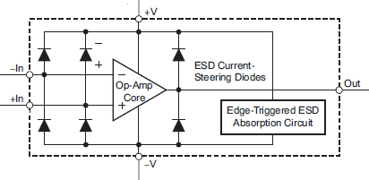
    Below is the typical ESD protection used in most modern devices:

    While some devices have special clamps to V- only that allow the inputs to go above the positive supply, almost all devices have ESD diodes, or unavoidable body didoes on the negative side. I am not aware of any devices that will allow and pins to go negative more than a diode drop. The TLV320x is actually quite liberal with a ±0.5V abs max, as most are ±0.3V.

    Of course, we recommend that large negative voltages be avoided, and external clamping didoes should be used (preferably Schottky), as well as a series current limiting resistor (recommend keeping the currents below 1mA).

  • Hi Paul,

    Thank you very much for the response. This is helpful, and I think validates the conclusion we'd come to. Given the nature of our current design, we can't guarantee the inputs will remain within the bounds of the datasheet, so we're forced into the steering diode with current limiting resistor solution.

    I just wanted to confirm, our scheme to protecting against negative going voltages is correct. If we select a diode with with a forward drop of no more than 450mV tied to the V- rail, with a series resistor of 500 ohms on the input to the comparator, we would limit the current to less than 1mA, which should allow the part to remain within the bounds of the datasheet. Does this sound like the approach you were referring to?

    Thank you again for your help,

    Tyler

  • Hello Tyler,

    Please see section 2.9 of the LM339 family appnote. While it is for a different device, the negative voltage clamping concept is the same.

    Application Design Guidelines for LM339, LM393, TL331 Family Comparators (Rev. A)

    My rule of thumb is 1k Ohm per volt of over voltage for the  series resistor. So if you are expecting a -10V input, then a minimum of 10k would be recommended. Again, the lower the clamp current, the better.

    The more current through the clamp diode, the higher the resulting forward voltage. So the lower the clamp current, the better. We recommend Shottky diodes, such as the BAT54x series, where the forward voltage is around 250-300mV at low currents (~1mA), as opposed to ~650mV for "regular" (1N4148 type) diodes.