This thread has been locked.

If you have a related question, please click the "Ask a related question" button in the top right corner. The newly created question will be automatically linked to this question.

TLV9061: Design of Battery Tester (Idea from SLAA868)

Part Number: TLV9061
Other Parts Discussed in Thread: INA260, CSD13202Q2

Hello,

For the testing of LiMnO2 batteries, i would like to build a few test circuits for internal use. LiMnO2 batteries are lithium batteries, that usually have a voltage of 3V, which drops down to 2V if they get empty. Also, these batteries tend do be only measurable on some mA of load, if measured in open circuit, the measurement is not very precise. Also, for lifetime estimation, i need a device that discharges the battery.

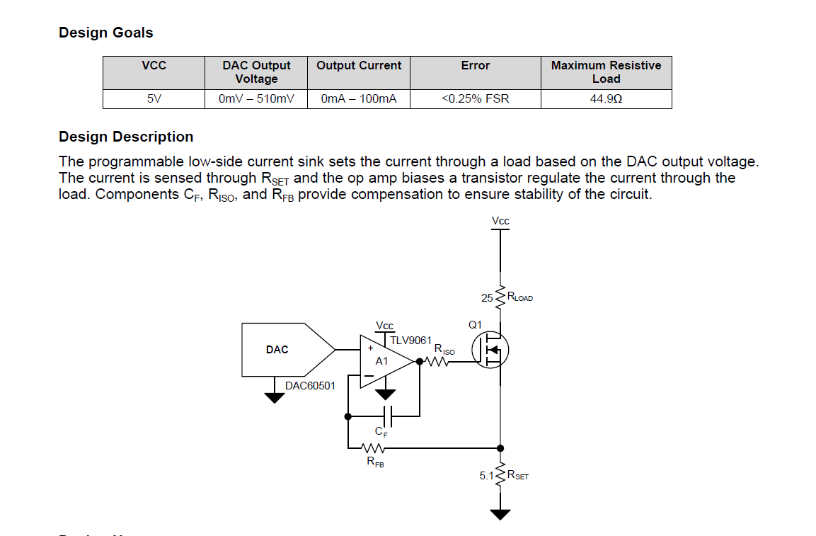
I found the constant current sink circuit in SLAA868:

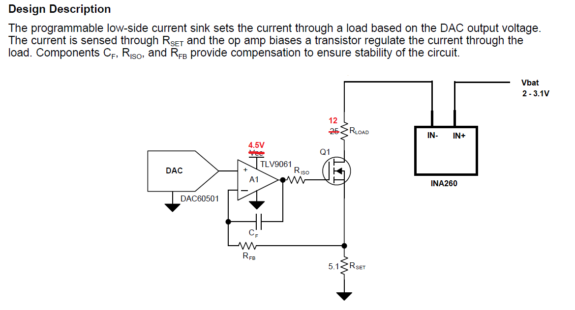
I modfied the schematic to show what it would look like in my circuit. There will be also INA260 for current measurement and voltage measurement

I've calculated the maximum resistivity load for an input of 2V, which would be 14.9 Ohms.
The maximum supply voltage of the DAC and OPAMP would be 4.5V, which comes from a filtered 5V source.

I'm unsure about the following parts:

1.) Is my schematic correct and would work?
2.) How is the mosfet choosen? What parameters are important? Which mosfet would suit best here?
3:) How are the Parts Rfb, Riso and Cf choosen?

  • Hi Jonathan,

    why not using a simple resistor for the discharging? Wouldn't be that precise enough?

    Kai

  • Johnathan,

    The 25 ohm R-load in the original drawing is the final output product (not part of the control system). In your case the battery is the R load. No resistor is needed here unless you want to limit current in case the FET shorts out (fault condition).  The 5.1 ohm resistor should be enough so "R-load" can be zero. Using a 1 ohm "Rload" resistor can help prevent a self oscillation (>200MHz) I have encountered with some fast FETs. 

    The MOSFET needs to be able to handle the battery voltage VDS, the maximum current IDS, and the maximum power VDS * IDS (consider your heat sink).  With the available gate drive the On resistance of the FET must be low enough.  (Rset + Ron[fet]) < VBat(min) / I[max] 

    Using your bandwidth requirement Fbw (how fast does it need to change and settle) 1/(6.28*Rfb*Cf) > Fbw.  1/(6.28*Riso*Cgate) > Fbw.  

    Do you need the minimum current load to be zero?  As drawn, the minimum load current is the greater of zero and (VIN + Vos) / Rset where VIN is the "zero" input voltage (is it really zero?) anf Vos is the input offset voltage of the op amp.


  • Hi Kai,

    A resistor is not suitable for this, since the resistor will change according to remaining voltage. With 10 Ohms at 3V, the current would be 300mA, with the same resistor at 2V only 200mA.

    In fact, when using SMPS, the current will go up because of efficiency. My application needs 3.3V 70mA, this translates to 230mW, because of efficiency loss, the input current at 2V, is way higher than at 3V, so a resistor discharge would produce exactly the wrong output.

  • Hi Ronald,

    Thanks for your reply,

    So i guess i will choose a 1 Ohm Resistor for Rload. According to the formula in the app note, the maximum power dissipation would be 300mW

    For example, when i look at the CSD13202Q2 Mosfet, which has RoJC+RoJA of 66.4 C/W, i except a temperature rise of around 20°C, which results in 45°C at 25°C ambient, so i guess i can operate without a heat sink here.

    For the fbw, 10kHz would be more than enough, so i assumed:

    1/(6.28 * 1kOhm * 10n) = 15923

    and

    1/(6.28 * 10kOhm * 1000pf) = 15923

    So i would choose
    Rfb = 1k
    Cf = 10n
    Riso = 10k

    Is this correct?

    The minimum current can be more than zero, but should be less than 5mA

    Regards,

    Jonathan

  • Johnathan,

    Those values should give about 72 degrees of phase margin. In other words, the loop will be stable

    Output current for 0mV input will be Vos / 5.1 ohm where Vos is in the range of +/-2mV, so output current could be between 0mA and 392uA (that's well under 5mA)