This thread has been locked.

If you have a related question, please click the "Ask a related question" button in the top right corner. The newly created question will be automatically linked to this question.

LMV722: Question about GBW and SR

Part Number: LMV722

Hi Team,

We now carry out the current sampling test, the test circuit is shown in the figure,signal frequency is 47kHz.

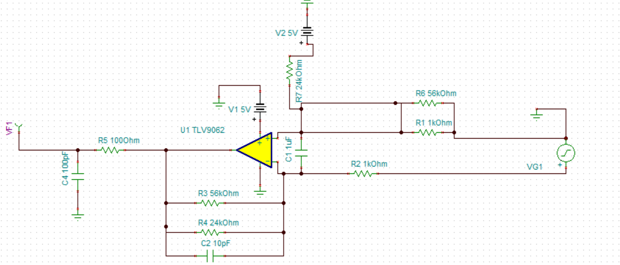
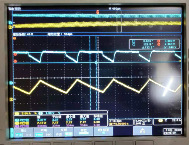
At first,we use the device is BW is 3.5MHz , SR is 8V/us,and the result is shown below:

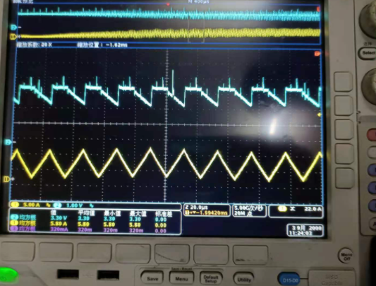
Now we use the LMV722,and  the result is:

I think it is because the GBW is too big to introduce noise, so I changed C2 to 100pF and got the result

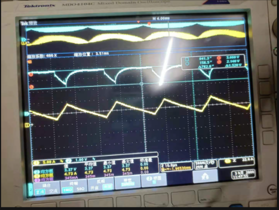
(Vout=3.5-16.8Vin,Vin=0~0.2)

I want to know the following question:

  • For the current situation, is a small BW more suitable for this situation?
  • According to my understanding, the higher the bandwidth, the faster the response speed. Even if I add a filter, my bandwidth is still relatively large. Why is there a greater delay?
  • For BW and SR, is SR more important for large signals (Vout>2V)? In this application, does BW or SR affect the final result? Is it related to large and small signals
  • How can I optimize the results to achieve the two ideal effects of the picture

Thanks for your help!

Jenson

  • Hi Jenson,

    you should urgently remove C1! That's very bad design practise.

    Kai

  • Former Member
    0 Former Member

    Hello Jenson,

    First, I will summarize the limitations of bandwidth and slew rate more generally. Then, I will add a few comments about your circuit.

    More generally:

    1. For small-signal inputs, the frequency of the output will match that of the input if you have enough bandwidth. There are a couple more things to keep in mind, however.
    2. If you have a small-signal input step, the speed will be determined by the closed-loop bandwidth. More bandwidth means a faster response. However, settling time will also be affected by stability.
    3. Even if the small-signal is within the bandwidth of the device, if the output is very large (say a large circuit gain) then the output can be limited by the slew-rate. This is called the full-power bandwidth.
    4. If the inputs are quickly pulled apart by a large step input, then your response time will be dominated by the slew rate.

    As you can see, the speed of your response will depend on bandwidth or slew rate depending on the application. However, in general you can understand this as the bandwidth is there to ensure a small-signal response and the slew rate is for large-signal responses.

    In your particular case, I would need to understand your circuit a bit better. Where are you measuring the input and where are you measuring the output? Is your output a current reading? What is the ideal output that you want?

    Judging just by the yellow curve, this looks like slewing. But I cannot tell because I don’t know the voltage change in time based off this alone. If you can answer my questions, then I think I will be able to give you a better answer.

    One last thing, as Kai has pointed out C1 could be an issue. Putting a capacitance on your IN- pin can lead to stability issues and this is a very large capacitance. Have you considered removing this component?

    Regards,
    Daniel

  • Former Member
    0 Former Member in reply to kai klaas69

    This thread is now being handled offline.