This thread has been locked.

If you have a related question, please click the "Ask a related question" button in the top right corner. The newly created question will be automatically linked to this question.

INA303-Q1: What are the alert pins used for in application note TIDUCY7

Part Number: INA303-Q1
Other Parts Discussed in Thread: INA303, DRV8313, INA302, INA301, TIDA-00778

Hi there, 

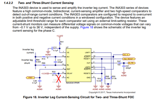
Right now I´m building a custom PCB for a motor controller that will use FOC. The driver/h-bridge that I use is DRV8313 and it needs additional current sensors to measure the phase currents. I found the TIDUCY7 application note (see link below) that uses INA303 in a similar fashion that I intended to have, but I can’t figure out how the alert pins are implemented? What do the system do when the alert pins are activated? Also, on "1.4.2.2 Two- and Three-Shunt Current Sensing" the authors also state: 

" The INA303 comparators are configured to respond to overcurrent in both positive and negative current conditions in a windowed configuration."

Note that this is for a topology that uses the INA303 on the inverter leg. Why do you need to configure the INA303 to both measure positive and negative current when the INA303 is on the inverter leg (current should only be able to go one way in this topology right)?. 

Best regards,

Carl 

----- 
Link: https://www.ti.com/lit/ug/tiducy7/tiducy7.pdf?ts=1615202042495&ref_url=https%253A%252F%252Fwww.google.com%252F


  • Carl,

    I agree with your assessment.  I will reach out to the author to confirm our understanding.  I will keep you updated.

    As for use of the alarm pin the way we both understand you can use the INA302 for two different levels of alerts.  You would need to adjust to have an additional alert monitor if you would like this feature.

    Otherwise you would use the INA301 which will have less pins and you only need to implement one alert per phase. 

  • Carl,

    I got a detailed reply from the author and it makes sense to me.

    "

    The inverter leg current will be bi-polar, which means the sense resistor on the inverter leg can have voltage drop in both the direction. The details can be seen in the diagram below

    In this diagram, I have considered only phase A and B (phase-C could be open or top switch conducting or bottom switch conducting). In the first figure, the phase-A winding carries a positive current and phase-B carries negative current, by turning on the top side switch of phase-A and bottom side switch of phase-B. When we apply PWM (ex: 20kHz), the switches are turned on and off at PWM frequency. During this, when phase -A top side switch is turned off, the motor (being an inductive load), will continue to carry positive current at phase-A winding and hence the motor current will find a free-wheeling path through the antiparallel diode of phase-A bottom side MOSFET/IGBT. In this case the voltage drop across the phase-A sense resistor is negative. In other combination similar to phase-B sense resistor getting a positive voltage drop, the phase-A sense resistor also get a positive voltage drop when the phase A winding is carrying negative current. So if we need the need the over current protection for both positive and negative winding current, we need a window comparator.


    We have used a level shift of 1.65V (VCC/2 for 3.3V supply) at the REF pin of INA303. The TIDA-00778 design guide also shows the bipolar current sense waveform at the output of INA303, with an offset of 1.65V, as shown below.


    "

  • Thank you so much Javier! Great answer! 

  • Hi Javier,

    a good explanation indeed Relaxed

    But isn't this a bit risky? The INA303 can only accept negative input voltages down to -0.1V:

    -8.68A x 5mR = -0.043V

    The least noise and ripple at the input of INA303 could destroy the INA303 as the absolute maximum negative input voltage of INA303 is -0.3V. So a brilliantly good GND routing on the PCB will be necessary...

    Kai