Other Parts Discussed in Thread: INA303, DRV8313, INA302, INA301, TIDA-00778
Hi there,
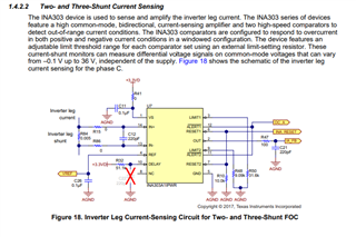
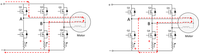
Right now I´m building a custom PCB for a motor controller that will use FOC. The driver/h-bridge that I use is DRV8313 and it needs additional current sensors to measure the phase currents. I found the TIDUCY7 application note (see link below) that uses INA303 in a similar fashion that I intended to have, but I can’t figure out how the alert pins are implemented? What do the system do when the alert pins are activated? Also, on "1.4.2.2 Two- and Three-Shunt Current Sensing" the authors also state:
" The INA303 comparators are configured to respond to overcurrent in both positive and negative current conditions in a windowed configuration."
Note that this is for a topology that uses the INA303 on the inverter leg. Why do you need to configure the INA303 to both measure positive and negative current when the INA303 is on the inverter leg (current should only be able to go one way in this topology right)?.
Best regards,
Carl
-----