This thread has been locked.

If you have a related question, please click the "Ask a related question" button in the top right corner. The newly created question will be automatically linked to this question.

AMC1300: AC voltage sensing. Noise at 130-160kHz

Part Number: AMC1300
Other Parts Discussed in Thread: AMC1200, AMC1200EVM, TLV9051, TLV6001, TLV9061

Hi,
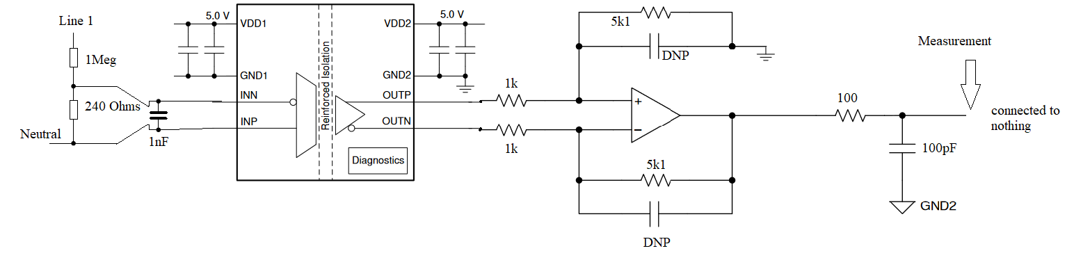
We are using the AMC1300 as a voltage sensing circuit (grid voltage). The application is an inverter connected to the 3phase grid. It is based on two level topologies.
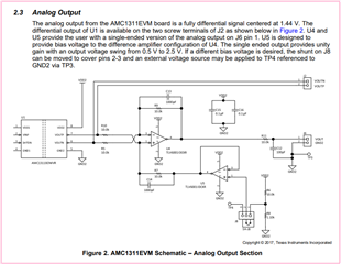
The schematic is the following:

The measurement is below in green:


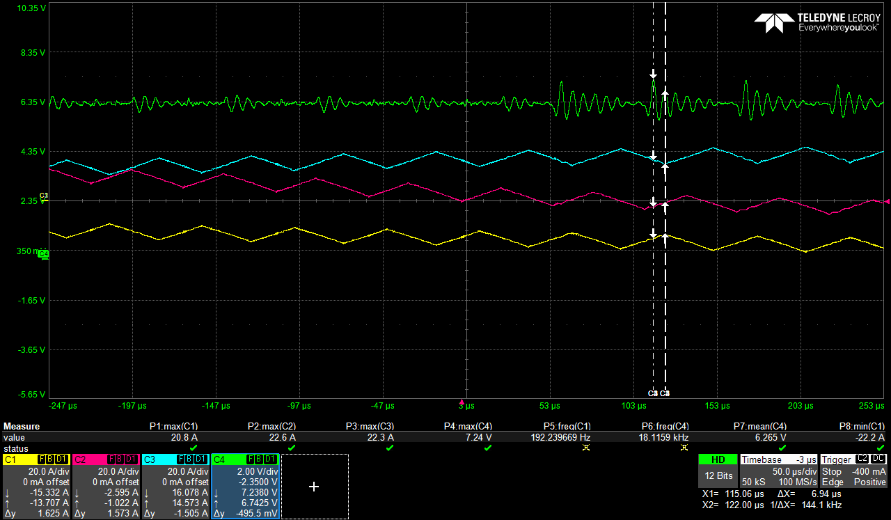
We have an oscillation measured at 144 kHz. That seems to be triggered by the switching stage. When the switching is off, the measurement is fine.
Have you already encountered is a similar phenomenon ?
Do you have any suggestions to remove those oscillations ?

Thank you for your help

Best regards,

  • Hi Julien,

    Following what Kai said, I would recommend increasing the size of the resistor on the output of the Diff to SE amplifier. 

    Thanks Kai! 

  • Thanks kai.  I am not sure to understand of which amplifier you are talking about. Based on Alexander's reply, we have inceased the 1k & 5k1 to 10k & 51k, whitout success.

    Regarding the isolated amplifier, based on the link you provide I am not quite sure of what to do:

    1. You violate the common mode input voltage range of -0.16V...VDD1. --> Is it applicable in our case ?

    2. The AMC1200 is designed for current measurement across low ohmic shunt resistance. But your R6 is rather high. This decreases the balance of input circuitry and results in decreased common mode rejection. --> We have a 240 Ohm instead of 6k7 on the post. So I think, it is not applicable to our design

    3. The AMC1200 provides true differential output signalling and needs to be terminated symmetrically. But you terminate it highly unsymmetrically and too low ohmically. See the AMC1200EVM for a suited output circuit. --> I think we have symetrical output, haven't we ?

  • Thanks Alexander. See upper post for my answer to both of you.

  • Hi Julien,

    How is your high-side ground connected? Is it tied to INN as shown on the first page of the datasheet?

    Not shown in the schematic provided and may explain why this oscillation is not being rejected at the input of the isolated amplifier. 

    What are the other measurements shown in the screen capture? 

    Can you measure at the input and output of the AMC1300 to confirm where this oscillation is introduced into the measurement?  

  • Hi Alexander,

    Thanks for your answer.

    Yes INN is connected to GND1. And there is a small mistake on my schematic the INN is connected to neutral and the INP to middle point of the voltage divider.

    The other measurements on scope capture are phase currents.

    I have tried to look at the input and output of the amc1300 but once I put a diff probe on the measurements, it amplifies the oscillations and I quickly get an OVP from the system.

  • Hi Julien,

    What is the bus voltage that you are attempting to measure? 

    Can you measure INP/INN/OUTP/OUTN individually without causing an OVP?

  • Hi Alexander,

    The bus voltage is the DC link of an inverter that is grid tied on the AC side.

    We have tried to measure INP/INN/OUTP/OUTN individually with a differential voltage probe but it worsen the phenomenon.

    We have also measure the DC link with a differential voltage probe and it is fine (no oscillation).

    We have filtered the bridge divider with a low pass filter @ 60 kHz, it seems that it has cleared the measure but the bandwidth of the measure is altered. We hope it will be enough for the system protection and loop regulation.

  • Hi Julien,

    I'm not sure why the extra capacitance of the probe would cause this phenomenon. Perhaps layout related? 

    I'm happy to hear at least that you have found a solution that appears to work. Please let me know if I can be of further assistance. 

  • Hi Alexander,

    I don't know if it's related to a layout issue. I think the solution will work this time.

    However in the future designs, we need to rely on the bandwidth of the datasheet because in our power applications, we often require 100 kHz or more (Overvoltage protection and harmonics distortion mainly).

    Thanks for your help!

  • Hi Julien,

    by enhancing your differential amplifier I meant not only increasing the resistances but also to mount suited capacitors (here C13 and C14). Also increase R11 from 100R to at least a couple of kOhms. Adjust the involved capacitor values to your needs.

    For best common mode rejection use identical resistors in the differential amplifier (5k...10k). Add another gain stage later, if you need more gain.

    Eventually you could take a better (faster) OPAmp compared to the TLV6001, like the TLV9051 or TLV9061 e.g. This could improve the common mode rejection. And you could experiment with a "3 OPAmp" INA instead of a simple differential amplifier. Play a bit with the balance of the passive common mode filters in front of the "3 OPAmp" INA. This can help to enhance the overall common mode rejection.

    Also, take an isolation amplifier with a higher bandwidth, like the AMC1300B, e.g.

    Kai