This thread has been locked.

If you have a related question, please click the "Ask a related question" button in the top right corner. The newly created question will be automatically linked to this question.

TLV3502: Scope output does not fit in the idea

Part Number: TLV3502

Hi TI expert

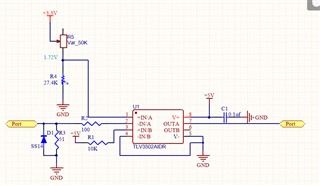
I would like to confirm if the circuit of their TLV 3502 is okay.

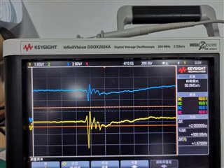
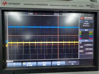
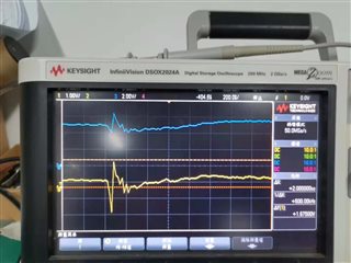
But with oscilloscopes, it doesn't fit the idea to show the waveform
why  the output waveform, not always parallel line, is high level?

Please refer as attached screenshot.

  • Li

    Would it be possible to capture the waveform of the supply voltage applied to V+.  

    Also, please avoid using the ground clip of the oscilloscope lead when monitoring the output.

    It is always best if you can monitor signals using as short of a ground connection as possible.

    Frequently I create a small coil of wire and connect this to ground; their is a ground sleeve close to the probe tip that the coil of wire can make contact with.

    By using this technique, you can avoid signals being inductively coupled into the waveform.

    We can also further discuss offline.  I will reach out directly on Monday to see how I can help resolve.

    Chuck

  • Hi Li,

    so there's no input signal coming from the left and the input is completely unconnected?

    In any case I would connect a 10...100n filtering cap from pin 1 to signal ground.

    I think Chuck means something like this?

    Using such a scope probe is mandatory when doing scope measurements in HF circuits, and the TLV3502 IS a HF chip!

    Also, follow HF design practises. Especially having a solid ground plane is very good idea Relaxed

    Kai

  • Awesome picture Kai, thank you for attaching and good suggestion

    Li, it seems like there is just something fundamental missing that is causing this response so let's discuss offline.  If we find something interesting to share on the forum, we will post.

    Chuck