


Other Parts Discussed in Thread: INA129-HT, OPA2333-HT, INA128-HT
Hello,
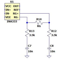
I have a question concerning the stability of the INA333-HT at 210 degC. The data states that if this device is going to be operated at 210 degC there must be an RC series network added at pin 1 and at pin 8 (the negative terminals of the input stage amplifiers) with both referenced to ground. The recommended values are a 10nF capacitor and a 3.5kohm resistor. I am limited to resistor values of 1k, 4.99k, and 10k and capacitor values of 10nF and 33nF due to temperature ratings and package requirements. This will be a rework to my current build to add these networks; so space is critical. Options I am considering are:
- 10nF and 4.99kohm: most desirable option if it will work
- 33nF and 1kohm: possible if the 33nF is not too large
- 10nF and 3.33kohm (10k//4.99k): would like to avoid stacking resistors
How much tolerance is allowed in the RC network? Also, can you take a look at the picture below to make sure I understand the placement of these networks:
Finally, my ideal gain is ~84V/V. Will I need to increase this gain in addition to the RC networks for the INA to be stable at higher temperatures? Also, is it possible for instability to cause the INA to have what looks like unity gain when the RC networks mentioned above are not connected and G=84V/V (given that all other requirements are met, such as DC return path is provided on inputs, common mode input range is not violated, Vref is from a low impedance source, etc.)?
Thank you,
Brandon
