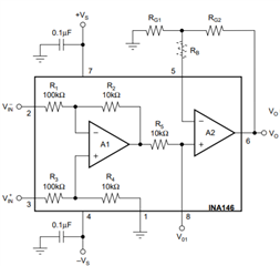
I have a simple AC circuit with a 100 ohm load. I've two INA146 chips (a differential op-amp with offset and second op-amp for gain). The output will go into a MCU at 3v. I use two voltage offsets to keep the common mode above the minimum for the voltage I'm going to measure. I then (wrongly?) set the resistors and offset to take up as much resolution as possible. The INA146 seems to have a problem going below 0.3v so I choose values to keep within about 2.8v-0.4v at peak AC.
The R4 and R1 resistors are a voltage divider as there's an internal 10k. I choose the values to get 1.5v at 0v AC (This should probably be 1.2v actually).
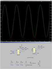
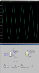
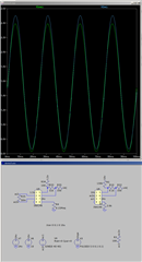
As the load is constant I then simulate with different voltages. What I've found is the voltage read is consistent but the current read becomes more skewed as voltage increases. Not sure is skewed is the correct word but you can see what I mean by the attached images.
The question of course, is whether it's accurate and if so any means to resolve it? I need both to be accurate with minimal phase as using them in real/apparent power factor measuring.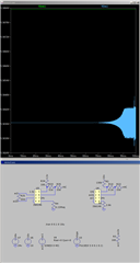

-
Ask a related question
What is a related question?A related question is a question created from another question. When the related question is created, it will be automatically linked to the original question.