This thread has been locked.

If you have a related question, please click the "Ask a related question" button in the top right corner. The newly created question will be automatically linked to this question.

INA190: Negative common mode voltage

Part Number: INA190

Hi,

I'm designing a battery powered current meter with the INA190A3 (gain 100V/V). So the floating power supply of the INA190 will have its ground tied to the negative input of the amp IN-. I want the user to be able to connect the inputs IN+ and IN- either way around with their device under test. Even though the voltage drop across the inputs will only be 40mV at most, if I add 1k resistors to inputs to limit current, can I safely operate the amp indefinitely with up to 5V difference between IN+ and IN- with polarity either way around? So if IN+=[+5] and IN-=[0]V, as well as IN+=[-5] and IN-=[0]V.

Thanks.

Shailen.

  • Hi Shailen,

    can you please show a schematic?

    Would also be important to know what is going on at the other pins of INA190 during this torture. Please also tell why the overvoltage at the inputs is limited to only 5V.

    Kai

  • Hi Kai,

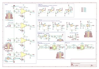
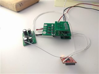
    I've designed and built an auto-switching digital current meter (schematic attached), that uses multiple shunts with their own INA190, and comparators to look for 2/3 voltage swing level of lower current amplifiers, where the output of a comparator then drives a low resistance MOSFET to switch off the shunt limiting the differential voltage input to safe levels, so saving amplifier and keeping burden voltage low. I'm using INA190A3 which are x100 gain, therefore the maximum difference between IN+ and IN- will be ~20mV before MOSTFETs kick in, as my threshold is 2V on output of INA190 for comparators. This design is uni-directional, but now I'm thinking of implementing window comparators, so I can use ref voltage on INA190 to measure currents in both directions. I want to use the inputs on the INA190 much like a multimeter where you can connect the inputs either way around. My circuits in schematic are simple, but just complicated by the fact I used connectors to keep the current sense amplifiers, power supply, comparators and ADC on separate boards in case it didn't work so each module could be useful on its own. It will be battery powered with -ve of battery connected to IN- on INA190.

    Thanks,

    Shailen.

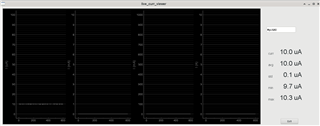
    sb_dynamic_multi_decade_ammeterbench_testingpython_live_gui

  • Hi Shailen,

    so GNDS=GNDA=H2 and H1=-5V...+5V while R5...R12=1k?

    Should work.

    Mount a 1N4002 protection diode from the output of LT1086 to its input, though.

    Kai

  • Hey Shailen,

    As long as the input voltages are within the Absolute Maximum ratings (section 6.1), then there is nothing to worry about with damaging the device.

    Since +5V is within the Abs Max differential input of +42V, then this is perfectly acceptable and thus no input resistors are necessary. I am confused about the scenario you mention with IN+ = [-5] and IN-=[0V]. Are these voltage with respect to the ground of the INA190? How would this come about? If this is true, then this would be a violation because no input voltage (with respect to ground), should ever go below -0.3V according to the Abs Max ratings. In this case, the INA190 would need input resistors to limit input current to under 5mA. So 5V/5mA = 1kΩ, although I would go with something bigger to limit current to 3mA for margin of safety.

    As long as the ground of the INA190 is the same as the ground of the 3.3V supply source, the ADC, then there should be no problems with ground loops here.

    Keep in mind that the reference voltage will definitely be needed if the differential input connection can be flipped. So if Vs=3.3V, then first-order full scale range is (3.3V/2)/100V/V = 16.5mV, not accounting for swing to rail limitations.

    Hope this help and sorry for the delay.

    Best,

    Peter